Foxconn P41A-G English Manual. - Page 22
Fan Connectors : CPU_FAN, SYS_FAN
 |
View all Foxconn P41A-G manuals
Add to My Manuals
Save this manual to your list of manuals |
Page 22 highlights
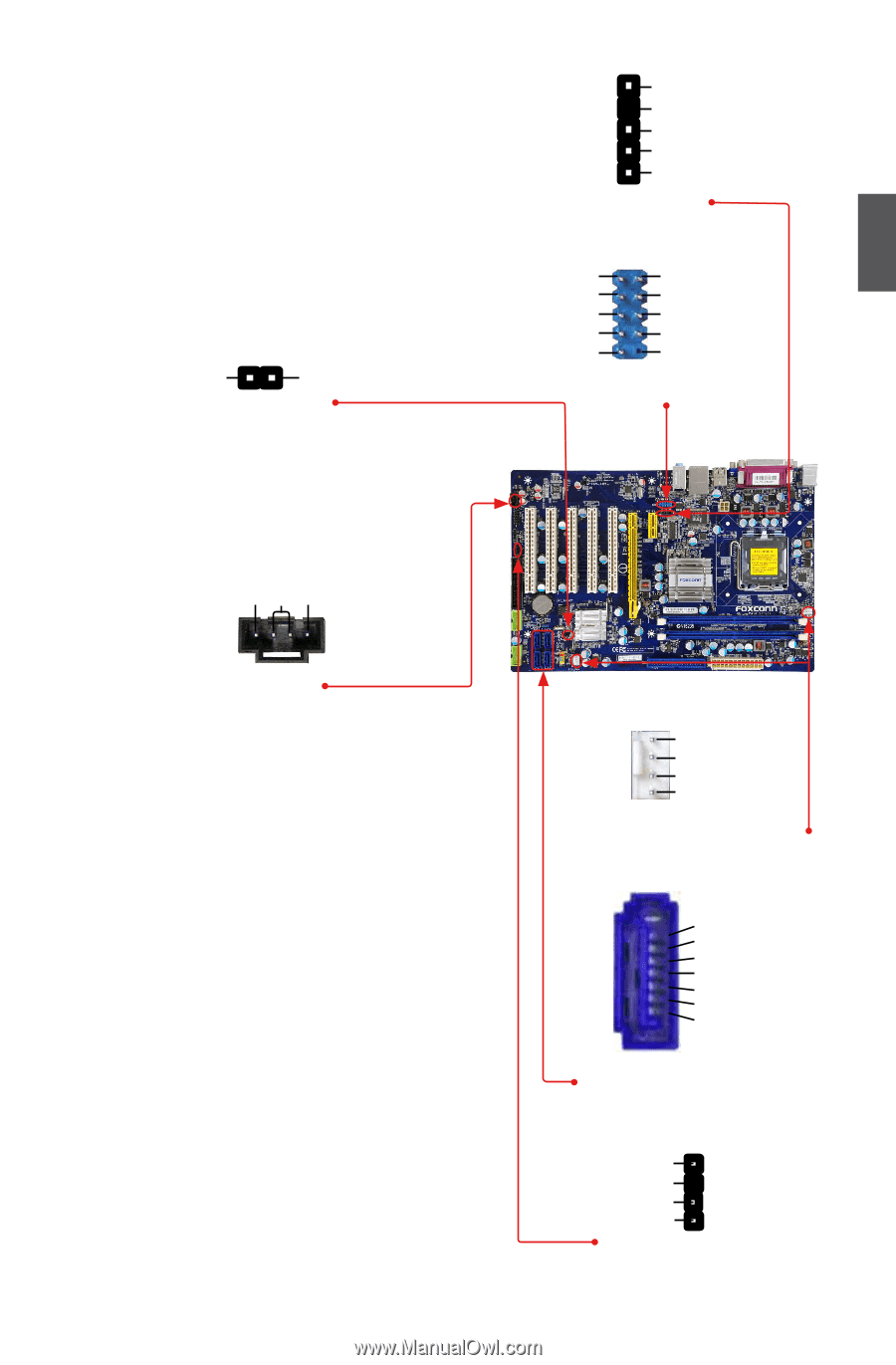
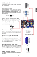
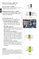
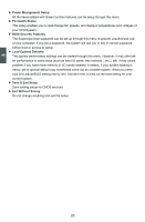
IrDA Connector : IR This connector supports infrared wireless trans-mitting and receiving device. COM Connector : COM2 User must purchase another RS232 cable with a 9pin D-sub connector at one end to connect with the external RS232 device and another end with 10-pin female connector to connect with COM2 connector in the motherboard. INTRUDERJ 1 INTR GND Chassis Intrusion Alarm Connector : INTR The connector can be connected to a security switch on the chassis. The system can detect the chassis intrusion through the function of this connector. If eventually the chassis is closed, the system will send a message out. CD_L GND CD_R 1 CD_IN Audio Connector : CD_IN CD_IN is a Sony standard audio connector, it can be connected to a CD/DVD-ROM drive through a CD/DVD audio cable. Fan Connectors : CPU_FAN, SYS_FAN There are two main fan headers on this motherboard. The fan speed can be controlled and monitored in "PC Health Status" section of the BIOS Setup. These fans can be automatically turned off after the system enters S3, S4 and S5 sleeping states. Serial ATA Connectors : SATA_1/2/3/4 The Serial ATA connector is used to connect with SATA Hard Disk or CD devices which support this feature. The current Serial ATA II interface allows up to 300MB/s data transfer rate. Speaker Connector : SPEAKER The speaker connector is used to connect speaker of the chassis. 15 15 1 2 3 4 5 IR +5V EMPTY IRRX GND IRTX RLSD SOUT GND RTS RI 12 9 10 SIN DTR DSR CTS EMPTY COM2 1 GND POWER SENSE CONTROL CPU_FAN/SYS_FAN 1 GND TX+ TXGND RXRX+ GND SATA_1/2/3/4 SPKJ EMPTY NC SPKJ SPEAKER 2
-
 1
1 -
2
-
3
-
4
-
5
-
6
-
7
-
8
-
9
-
10
-
11
-
12
-
13
-
14
-
15
-
16
-
 17
17 -
 18
18 -
 19
19 -
 20
20 -
 21
21 -
 22
22 -
 23
23 -
 24
24 -
 25
25 -
 26
26 -
 27
27 -
28
-
29
-
30
-
31
-
32
-
33
-
34
-
35
-
36
-
37
-
38
-
39
-
40
-
41
-
42
-
43
-
44
-
45
-
46
-
47
-
48
-
49
-
50
-
51
-
52
-
53
-
54
-
55
-
56
-
57
-
58
-
59
-
60
-
61
-
62
-
63
-
64
-
65
-
66
-
67
-
68
-
69
-
70
-
71
-
72
 |
 |