Foxconn P41A-G English Manual. - Page 23
S/PDIF OUT Connector : SPDIF_OUT, Audio Connector : F_AUDIO, F_USB1/2
 |
View all Foxconn P41A-G manuals
Add to My Manuals
Save this manual to your list of manuals |
Page 23 highlights
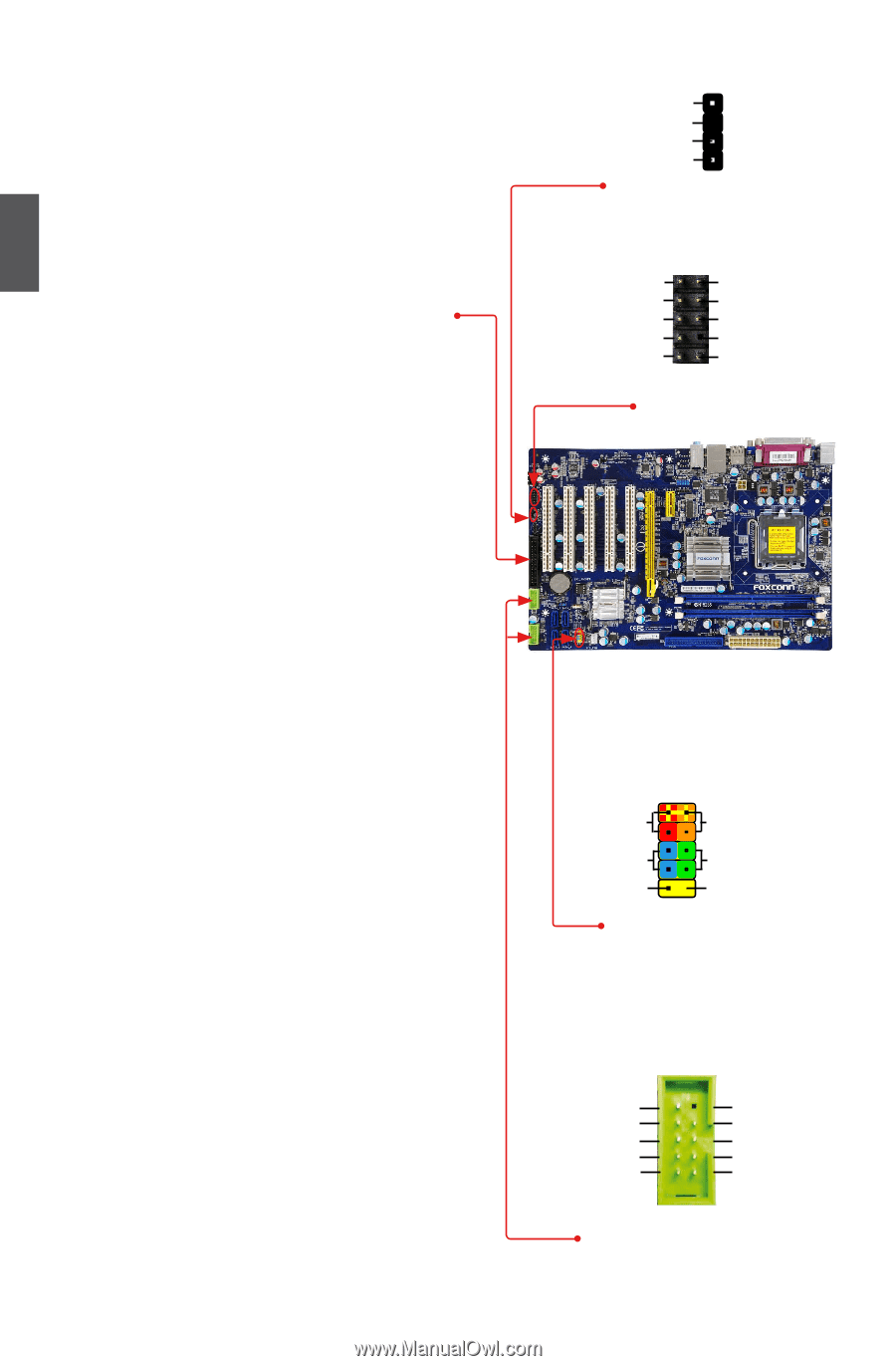
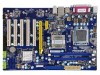
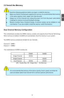
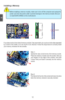
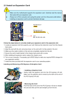
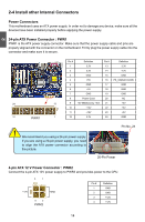
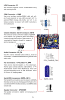
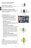
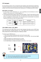
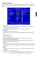
2 S/PDIF OUT Connector : SPDIF_OUT The connector is used for S/PDIF output. Audio Connector : F_AUDIO The audio connector supports HD Audio standard. It provides the Front Audio output choice. Floppy Disk Drive Connector : FLOPPY This motherboard includes a standard floppy disk drive (FDD) connector, supporting 360KB, 720KB, 1.2MB, 1.44MB, and 2.88MB FDDs. Front Panel Connector : FP1 This motherboard includes one connector for connecting the front panel switch and LED Indicators. Hard Disk LED Connector (HDD-LED) Connect to the chassis front panel IDE indicator LED. It indicates the active status of the hard disks. This 2-pin connector is directional with +/- sign. Reset Switch (RESET-SW) Attach the connector to the Reset switch on the front panel of the case; the system will restart when the switch is pressed. Power LED Connector (PWR-LED) Connect to the power LED indicator on the front panel of the chassis. The Power LED indicates the system's status. When the system is in operation (S0 status), the LED is on. When the system gets into sleep mode (S1) , the LED is blinking; When the system is in S3/S4 sleep state or power off mode (S5), the LED is off. This 2-pin connector is directional with +/- sign. Power Switch Connector (PWR-SW) Connect to the power button on the front panel of the chassis. Push this switch allows the system to be turned on and off rather than using the power supply button. F_USB1/2 In addition to the four USB ports on the rear panel, this product also provides two 10-pin USB header on its motherboard. By connecting through USB cables with them, user can quickly expand another four USB ports on the front panel. 16 16 +5V 1 EMPTY 2 SPDIF_OUT 3 GND 4 SPDIF_OUT PORT1_L PORT1_R PORT2_R SENSE_SEND PORT2_L 12 9 10 AUD_GND PRESENCEJ SENSE1_RETURN EMPTY SENSE2_RETURN F_AUDIO 1 + HDD-LED- 2 + PWR-LED - RESET-SW PWR-SW NC EMPTY 9 10 FP1 12 VCC DD+ GND EMPTY VCC D- D+ GND NC 9 10 F-USB 1/2
-
 1
1 -
2
-
3
-
4
-
5
-
6
-
7
-
8
-
9
-
10
-
11
-
12
-
13
-
14
-
15
-
16
-
17
-
 18
18 -
 19
19 -
 20
20 -
 21
21 -
 22
22 -
 23
23 -
 24
24 -
 25
25 -
 26
26 -
 27
27 -
 28
28 -
29
-
30
-
31
-
32
-
33
-
34
-
35
-
36
-
37
-
38
-
39
-
40
-
41
-
42
-
43
-
44
-
45
-
46
-
47
-
48
-
49
-
50
-
51
-
52
-
53
-
54
-
55
-
56
-
57
-
58
-
59
-
60
-
61
-
62
-
63
-
64
-
65
-
66
-
67
-
68
-
69
-
70
-
71
-
72
 |
 |