Foxconn Z75A-S User manual - Page 22
Chassis Intruder Alarm Connector : INTR, Hard Disk LED Connector HDD-LED
 |
View all Foxconn Z75A-S manuals
Add to My Manuals
Save this manual to your list of manuals |
Page 22 highlights
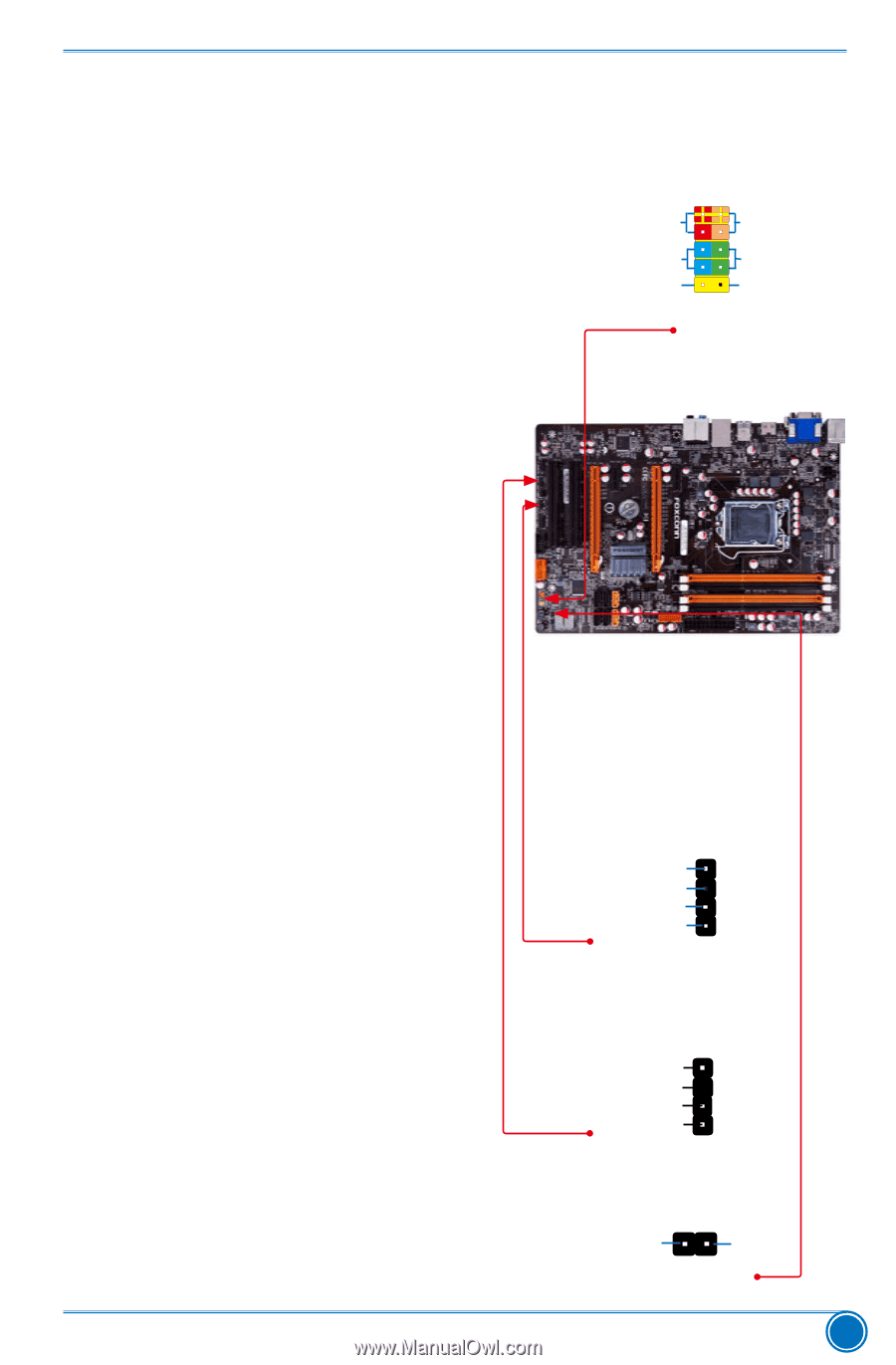
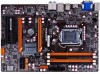
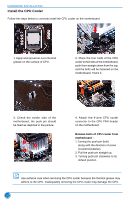
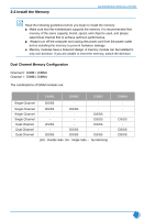
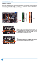
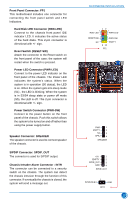
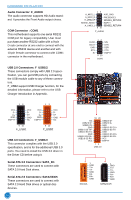
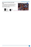
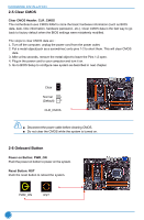
Front Panel Connector: FP1 This motherboard includes one connector for connecting the front panel switch and LED Indicators. Hard Disk LED Connector (HDD-LED) Connect to the chassis front panel IDE indicator LED. It indicates the active status of the hard disks. This 2-pin connector is directional with +/- sign. Reset Switch (RESET-SW) Attach the connector to the Reset switch on the front panel of the case; the system will restart when the switch is pressed. Power LED Connector (PWR-LED) Connect to the power LED indicator on the front panel of the chassis. The Power LED indicates the system's status. When the system is in operation (S0 status), the LED is on. When the system gets into sleep mode (S1) , the LED is blinking; When the system is in S3/S4 sleep state or power off mode (S5), the LED is off. This 2-pin connector is directional with +/- sign. Power Switch Connector (PWR-SW) Connect to the power button on the front panel of the chassis. Push this switch allows the system to be turned on and off rather than using the power supply button. Speaker Connector: SPEAKER The speaker connector is used to connect speaker of the chassis. S/PDIF Connector: SPDIF_OUT The connector is used for S/PDIF output. Chassis Intruder Alarm Connector : INTR The connector can be connected to a security switch on the chassis. The system can detect the chassis intrusion through the function of this connector. If eventually the chassis is closed, the system will send a message out. HARDWARE INSTALLATION 12 + + HDD-LED - PWR-LED - RESET-SW PWR-SW NC EMPTY 9 10 FP1 PWR 1 EMPTY 2 NC 3 SPKJ 4 SPEAKER +5V 1 EMPTY 2 SPDIF_OUT 3 GND 4 SPDIF_OUT INTRUDERJ 1 GND INTR 15
-
 1
1 -
2
-
3
-
4
-
5
-
6
-
7
-
8
-
9
-
10
-
11
-
12
-
13
-
14
-
15
-
16
-
 17
17 -
 18
18 -
 19
19 -
 20
20 -
 21
21 -
 22
22 -
 23
23 -
 24
24 -
 25
25 -
 26
26 -
 27
27 -
28
-
29
-
30
-
31
-
32
-
33
-
34
-
35
-
36
-
37
-
38
-
39
-
40
-
41
-
42
-
43
-
44
-
45
-
46
-
47
-
48
-
49
-
50
-
51
-
52
-
53
-
54
-
55
-
56
-
57
-
58
-
59
-
60
-
61
-
62
-
63
-
64
-
65
-
66
-
67
-
68
-
69
-
70
-
71
-
72
-
73
-
74
-
75
-
76
-
77
-
78
-
79
-
80
-
81
-
82
-
83
-
84
-
85
-
86
-
87
-
88
-
89
-
90
-
91
-
92
-
93
-
94
-
95
-
96
-
97
-
98
-
99
-
100
-
101
-
102
-
103
-
104
-
105
-
106
-
107
-
108
 |
 |