Frigidaire FFLE2022MW Installation Instructions - Page 8
Clearance Requirements
 |
View all Frigidaire FFLE2022MW manuals
Add to My Manuals
Save this manual to your list of manuals |
Page 8 highlights
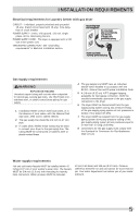
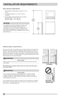
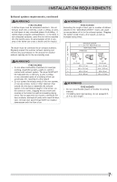
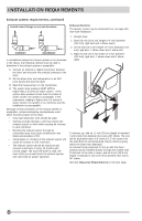
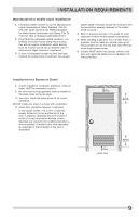
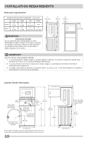
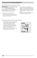
INSTALLATION REQUIREMENTS Exhaust system requirements, continued Install male fittings in correct direction: Exhaust direction The laundry center may be exhausted four (4) ways with rear flush installation: CORRECT INCORRECT In installations where the exhaust system is not described in the charts, the following method must be used to determine if the exhaust system is acceptable: 1 Connect an inclined or digital manometer between the dryer and the point the exhaust connects to the dryer. 2 Set the dryer timer and temperature to air fluff (cool down) and start the dryer. 3 Read the measurement on the manometer. 4 The system back pressure MUST NOT be higher than 0.6 inches of water column. If the system back pressure is less than 0.6 inches of water column, the system is acceptable. If the manometer reading is higher than 0.6 inches of water column, the system is too restrictive and the installation is unacceptable. Although vertical orientation of the exhaust system is acceptable, certain extenuating circumstances could affect the performance of the dryer: • Only rigid metal duct work should be used. • Venting vertically through a roof may expose the exhaust system to down drafts causing an increase in vent restriction. • Running the exhaust system through an uninsulated area may cause condensation and faster accumulation of lint. • Compression or crimping of the exhaust system will cause an increase in vent restriction. • The exhaust system should be inspected and cleaned a minimum of every 18 months with normal usage. The more the dryer is used, the more often you should check the exhaust system and vent hood for proper operation. 1. Straight back 2. Down (8 inch [20.3 cm] length of 4 inch diameter [102 mm] rigid duct and 1 elbow down) 3. Left (8 inch [20.3 cm] length of 4 inch diameter [102 mm] rigid duct, 1 elbow down and 1 elbow left) 4. Right (8 inch [20.3 cm] length of 4 inch diameter [102 mm] rigid duct, 1 elbow down and 1 elbow right) To exhaust up, add an 11 inch (28 cm) length of standard 4 inch (102 mm) diameter duct and a 90° elbow. The unit will be positioned about 4.5 inches (11.5 cm) away from the wall (flush to wall exhausting may be done by going below the dryer then sideways). An exhaust hood positioned to line up with the dryer exhaust can be installed directly through the outside wall. To exhaust to the side or down, add an 8 inch (20.3 cm) length of standard 4 inch (102 mm) diameter duct and a 90° elbow. See also Clearance Requirements on the next page. 8
-
 1
1 -
2
-
 3
3 -
 4
4 -
 5
5 -
 6
6 -
 7
7 -
 8
8 -
 9
9 -
 10
10 -
 11
11 -
 12
12 -
 13
13 -
14
-
15
-
16
-
17
-
18
-
19
-
20
-
21
-
22
-
23
-
24
-
25
-
26
-
27
-
28
-
29
-
30
-
31
-
32
-
33
-
34
-
35
-
36
-
37
-
38
-
39
-
40
-
41
-
42
-
43
-
44
-
45
-
46
-
47
-
48
-
49
-
50
-
51
-
52
-
53
-
54
-
55
-
56
-
57
-
58
-
59
-
60
-
61
-
62
-
63
-
64
 |
 |
