Frigidaire FGF319KB Installation Instructions (All Languages) - Page 5
Please Read Carefully
 |
View all Frigidaire FGF319KB manuals
Add to My Manuals
Save this manual to your list of manuals |
Page 5 highlights
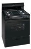
30" GAS RANGE INSTALLATION INSTRUCTIONS (For Gas Venturi models with Electric Ignition) Checking Manifold Gas Pressure Disconnect the range and its individual shut-off valve from the gas supply piping system during any pressure testing of that system at test pressures greater than 14" of water column pressure (approximately 1/2" psig). If it should be necessary to check the manifold gas pressure, connect manometer (water gauge) or other pressure device to the top burner right rear orifice. Using a rubber hose with inside diameter of approximately 1/4," hold tubing down tight over orifice. Turn burner valve on. 6. Operation of Surface Burners Operation of electric igniters should be checked after range and supply line connectors have been carefully checked for leaks and range has been connected to electric power. Check Surface Burners To check for proper lighting, push in and turn a surface burner knob to the LITE position. Each burner should light within four (4) seconds in normal operation. Once the burner lights, the knob should be rotated out of the LITE position. Try each knob separately until all burner valves have been checked. For an accurate pressure check have at least two (2) other top burners burning. Be sure the gas supply (inlet) pressure is at least one inch above specified range manifold pressure. The gas supply pressure should never be over 14" water column. When properly adjusted for Natural Gas the manifold pressure is 4." (For LP/Propane Gas the manifold pressure is 10.") 5. Read electrical connection details below and connect electricity to range. Before servicing, disconnect electrical supply at circuit breaker, fuse or power cord. Electric Requirements: A dedicated, properly grounded and polarized branch circuit protected by a 15 amp. circuit breaker or time delay fuse. See serial plate for proper voltage. Extension Cord Precautions: Because of potential safety hazards under certain conditions, we strongly recommend against the use of any extension cord. However, if you still elect to use an extension cord, it is absolutely necessary that it be a UL listed 3-wire grounding type appliance extension cord and that the current carrying rating of the cord in amperes be equivalent to or greater than the branch circuit rating. Such extension cords are obtainable through your local service organization. PLEASE READ CAREFULLY! For personal safety, this product must be properly grounded. Grounding Instructions The power cord of this appliance is equipped with a 3-prong (grounding) plug which mates with a standard 3-prong grounding wall receptacle to minimize the possibility of electric shock hazard from this appliance. The customer should have the wall receptacle and circuit checked by a qualified electrician to make sure the receptacle is properly grounded and polarized. Where a standard two-prong wall receptacle is encountered, it is the personal responsibility and obligation of the customer to have it replaced with a properly grounded three-prong wall receptacle. DO NOT, UNDER ANY CIRCUMSTANCES, CUT OR REMOVE THE THIRD (GROUND) PRONG FROM THE POWER CORD. Air Shutter adjustment 7. Air adjustment The air shutter (adjustment) for each of the four top burners is located at the open end of the venturi tube and sets on the hood of the valve. Should the air shutter need adjusting, rotate the air shutter to allow more or less air into the burner tubes as needed. If the air is properly adjusted, the flame will be steady, relatively quiet, and have approximately 1/2" sharp blue cone. (Usually about the center of air shutter's ajustment.) If the flame is yellow in color, increase air shutter opening size. If the flame is a distinct blue, but lifting away from the burner, reduce the air shutter opening size. 8. Oven Burner Adjustments Operation of electric igniters should be checked after range and supply line connectors have been carefully checked for leaks and range has been connected to electric power. The oven burner is equipped with an electric control system as well as an electric oven burner igniter. These control systems require no adjustment. When the oven is set to operate, current will flow to the igniter. It will "glow" similar to a light bulb. When the igniter has reached a temperature sufficient to ignite gas, the electrically controlled oven valve will open and flame will appear at the oven burner. There is a time lapse from 30 to 60 seconds after the thermostat is turned ON before the flame appears at the oven burner. When the oven reaches the dial setting, the glowing igniter will go off. The burner flame will go "out" in 20 to 30 seconds after the igniter goes "OFF." To maintain any given oven temperature, this cycle will continue as long as the dial (or display) is set to operate. After removing all packing materials and literature from the oven: a) Set oven to BAKE at 300ºF. See Owner's Guide for operating instructions. b) Within 60 seconds the oven burner should ignite. Check for proper flame, and allow the burner to cycle once. Reset controls to off. c) Within 60 seconds the broil burner should ignite. Check for proper flame. Reset controls to off. 5
-
 1
1 -
 2
2 -
 3
3 -
 4
4 -
 5
5 -
 6
6 -
 7
7 -
 8
8 -
 9
9 -
 10
10 -
 11
11 -
12
 |
 |
