Frigidaire FGHT2055VF Installation Instructions - Page 1
Frigidaire FGHT2055VF Manual
 |
View all Frigidaire FGHT2055VF manuals
Add to My Manuals
Save this manual to your list of manuals |
Page 1 highlights
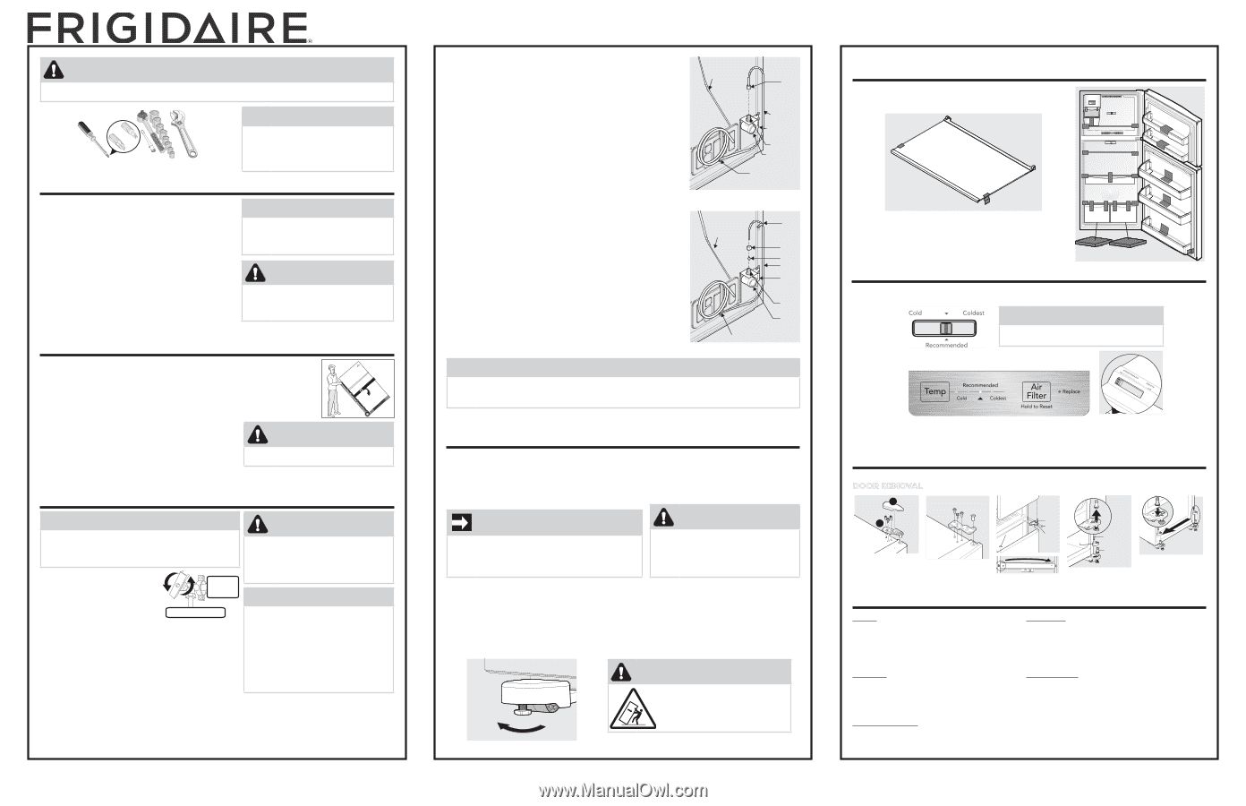
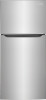
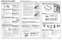
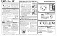
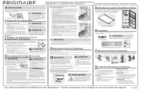
Installation Instructions for Top Mount Gallery/Professional Refrigerator This document should only be removed by the customer after installation. WARNING To avoid electric shock, which can cause death or severe personal injury, do not connect your refrigerator to an electrical power source until you have completed Step 3 of these instructions. Tools Necessary: #2 Square Bit or Quadrex Head Screwdriver (OR) OR Socket Adjustable Wrench Set Wrench Plastic Putty Knife NOTE Awl These installation instructions are provided only as a possible customer Plieorsption. We recommend you use a service or kitchen contracting professional to install your refrigerator. 1 Prepare The Installation Site Include these minimum guidelines in your site preparation: • Choose a place near a grounded electrical outlet. • Do not use an extension cord or an adapter plug. • Avoid direct sunlight and close proximity to a range, dishwasher or other heat source. • Floor should be level and able to support a fully loaded refrigerator. Allow the following clearances for ease of installation, proper air circulation, and plumbing and electrical connections: Sides & Top: 3/8 in. Rear: 1 in. NOTE Information about cabinetry construction for your new appliance is available for contractors. Call 1-800374-4432. CAUTION Room temperatures below 55°F (13°C) or above 110°F (43°C) will impair cooling ability of your refrigerator's compressor. 2 Transport Refrigerator To Site By now, you have already removed your refrigerator's shipping carton. You may still need to use a hand truck to move it through close spaces or entrances. If the refrigerator is larger than an entrance, consider 2 options: • Remove the entrance door if one exists. • Remove the refrigerator doors (see how in your Use & Care Guide). When using a hand truck: • Load refrigerator from side of cabinet only. CAUTION • Do not run retaining straps over handles. • Do not overtighten retaining straps. • Never use refrigerator handles to move Shifting the refrigerator from side to side may damage flooring. the refrigerator. • Remove packaging tape from doors only after the unit is in place. 3 Water Supply Connection NOTE CAUTION Automatic ice makers are optional accessories that may be installed in most at any time. Visit www.frigidaire.com for information about Ice Maker Kit 117000. To avoid property damage: • Use a water supply line made of stainless steel tubing or polyline. What you will need: • Ensure water supply complies House with local plumbing codes. • Basic Tools: adjustable wrench, flat- plumbing line NOTE blade screwdriver, and PhillipsTM screwdriver Water line hookup For homes with existing valves, • Access to a household Frigidaire recommends its Smart cold water line with water pressure between Choice® water line kit 5304437642 30 and 100 psi. (with a 6 ft. stainless steel water • A water supply line made of ¼ inch (6.4 mm) OD, copper or stainless steel tubing. To determine the length of tubing needed, measure the distance from the ice maker inlet valve at the back of the refrigerator to your cold water pipe. Then add approximately 7 line), and for homes without an existing valve, Frigidaire recommends its Smart Choice® water line kit 5304493869 (with a 6 ft. polyline water line). Please refer to www. frigidaire.com for more information. feet (2.1 meters), so the refrigerator can be moved out for cleaning (as shown). • A shutoff valve to connect the water supply line to your household water system. DO NOT use a self-piercing type shutoff valve. • Do not reuse compression fitting or use thread seal tape. • A compression nut and ferrule (sleeve) for connecting a copper water supply line to the ice maker inlet valve. To Connect Water Supply Line To the Ice Maker Inlet Valve: 1 Disconnect the refrigerator from the electric power source. 2 Place the end of water supply line into a sink or a bucket. Turn ON the water supply and flush the supply line until the water is clear. Turn OFF the water supply at the shutoff valve. 3 Remove the plastic cap from water valve inlet and discard the cap. 4 If you use copper tubing, slide brass compression nut, and then ferrule (sleeve) onto water supply line. Push water supply line into water valve inlet as far as it will go (¼ in. / 6.4 mm). Slide ferrule (sleeve) into valve inlet and finger tighten compression nut onto valve. Tighten another ½ turn with a wrench; DO NOT overtighten. See Figure 1. If you use braided flexible stainless steel tubing, the nut is already assembled on the tubing. Slide nut onto valve inlet and finger tighten nut onto valve. Tighten another ½ turn with a wrench; DO NOT overtighten. See Figure 2. 5 With steel clamp and screw, secure water supply line (copper tubing only) to rear panel of refrigerator as shown. 6 Coil excess water supply line (copper tubing only), about 2½ turns, behind refrigerator as shown and arrange coils so they do not vibrate or wear against any other surface. 7 To turn ice maker on, press the ice maker's On/Off power switch so the LED is steadily illuminated. 8 Turn ON the water supply at the shutoff valve and tighten any connections that leak. 9 Reconnect refrigerator to an electrical power source. Plastic Water Tubing to Ice Maker Fill Tube Brass Compression Nut Water Line Water Valve Bracket Valve Inlet Water Valve 6 ft minimum (1.8 m) braided flexible stainless steel water line from household water supply m(IonvcinlugdereefrnigoeFurgaightoutrurobeuint1gfoinr ctoleaanlloinwg.) Plastic Water Tubing to Ice Maker Fill Tube Clamp Brass Compression Nut Ferrule Sleeve Copper Line Water Valve Bracket Water Valve Inlet Water Valve Copper water line from household water supply (InmclouvdiengenreofurigFgheigrtauutborirnegou2int floorocpletoanailnlogw.) NOTE • The ice maker's fill valve may operate noisily if the household water supply is shut off. • After ensuring no water leaks exist at any connection, be sure to check for leaks again in 24 hours. 4 Final Positioning of Refrigerator If possible, use a hand truck to position the refrigerator directly in front of its cabinet enclosure. Be careful not to move the refrigerator beyond its water supply (copper tubing) connections. Plug in the power cord, and push the refrigerator straight back into place. IMPORTANT If you are installing your refrigerator without connecting it to a water supply (some models), make sure the ice maker's power switch is turned Off (see the Use & Care Guide for more details). CAUTION • Shifting the refrigerator from side to side may damage flooring. • Do not block the lower front of your refrigerator. Sufficient air circulation is essential for proper operation. • All 4 corners of the cabinet must rest firmly on the floor. • The cabinet should be level at the front and rear. • The refrigerator must be installed on a floor that is level and strong enough to support a fully loaded refrigerator. Setting the Anti-tip device: The Anti-tip brackets are located on the lower front corners of the cabinet. Lower the Anti-tip on each side clockwise until they contact the floor. Do not raise the cabinet. Lower WARNING The anti-tip device must be installed according to the instructions in your Use & Care Manual. Failure to do so will result in injury. Anti-Tip Bracket 5 Remove Internal Shipping Materials We use packing foam, clips and tape to secure the internal parts of your refrigerator for shipping. Once the refrigerator is in position, you can remove this material. Location of these materials may vary depending on your model. 6 Controls When changing controls, wait 24 hours before making additional adjustments. Freezer Control NOTE Allow 15 minutes for compressor to start after initial start up or power interruption. Refrigerator Control (Gallery/Professional Models) Humidity Control 7 Door Removal (if necessary) If you need to remove the doors to get your refrigerator into the house, please see DOOR REMOVAL in your Use & Care Manual. A Hinge B Pin Screws Hinge Hole Plug Center Hinge Door Stopper Door Stopper Screw Bottom Hinge Pin 8 Installation Checkoff List Doors ȽȽ Handles are secure and tight (some models) ȽȽ Door seals completely to cabinet on all sides ȽȽ Freezer door is level across the top Leveling ȽȽ Refrigerator is level, side to side and tilted ¼ in. (6 mm) front to back ȽȽ Cabinet is set solid on all corners ȽȽ Anti-tip bracket set Electrical Power ȽȽ House power turned on ȽȽ Refrigerator plugged in Ice Maker ȽȽ House water supply connected to refrigerator (ice maker installed) ȽȽ No water leaks present at all connections - recheck in 24 hours ȽȽ Ice Maker is turned ON (ice maker installed) Final Checks ȽȽ Shipping material removed ȽȽ Fresh Food and Freezer controls set ȽȽ Registration Card sent in Not satisfied with the installation of your refrigerator? Please contact the store from which you purchased your refrigerator. P/N: A18485501
-
 1
1 -
 2
2 -
 3
3
 |
 |