Frigidaire FGIF3061NF Service Data Sheet - Page 1
Frigidaire FGIF3061NF Manual
 |
View all Frigidaire FGIF3061NF manuals
Add to My Manuals
Save this manual to your list of manuals |
Page 1 highlights
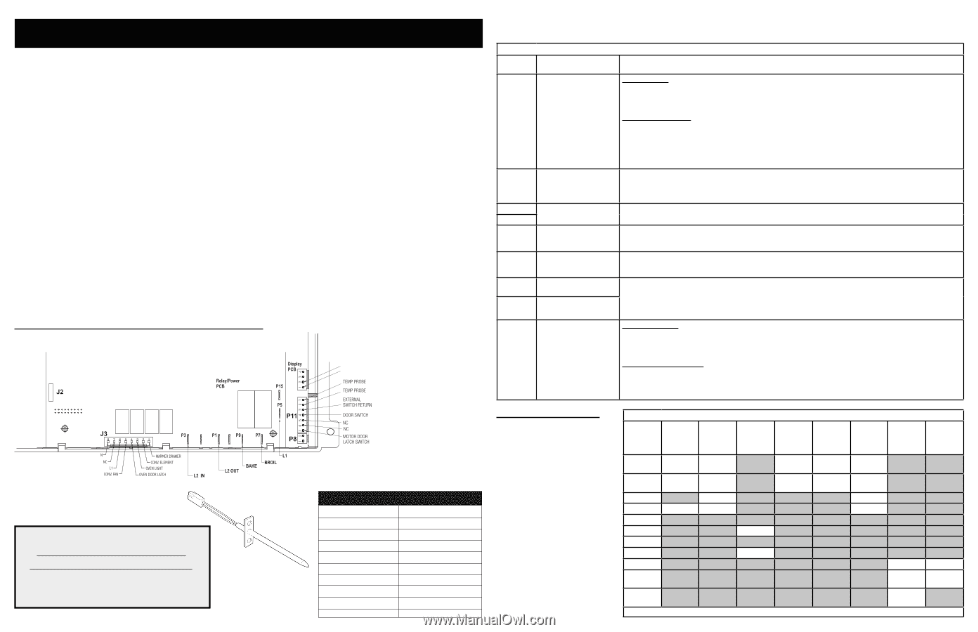
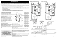
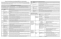
SERVICE DATA SHEET Electric Range with ES 540 Electronic Oven Control NOTICE - This service data sheet is intended for use by persons having electrical and mechanical training and a level of knowledge of these subjects generally considered acceptable in the appliance repair trade. The manufacturer cannot be responsible, nor assume any liability for injury or damage of any kind arising from the use of this data sheet. SAFE SERVICING PRACTICES To avoid the possibility of personal injury and/or property damage, it is important that safe servicing practices be observed. The following are examples, but without limitation, of such practices. 1. Before servicing or moving an appliance remove power cord from electrical outlet, trip circuit breaker to OFF, or remove fuse. 2. Never interfere with the proper installation of any safety device. 3. GROUNDING: The standard color coding for safety ground wires is GREEN or GREEN WITH YELLOW STRIPES. Ground leads are not to be used as current carrying conductors. It is extremely important that the service technician reestablish all safety grounds prior to completion of service. Failure to do so will create a potential safety hazard. 4. Prior to returning the product to service, ensure that: • All electric connections are correct and secure. • All electrical leads are properly dressed and secured away from sharp edges, high-temperature components, and moving parts. • All uninsulated electrical terminals, connectors, heaters, etc. are adequately spaced away from all metal parts and panels. • All safety grounds (both internal and external) are correctly and securely reassembled. Oven Calibration Set the electronic oven control for normal baking at 350°F. Obtain an average oven temperature after a minimum of 5 cycles. Press Stop keypad to end Bake mode. Temperature Adjustment 1. While in a non-cooking mode, press and hold the Bake key pad for 6 seconds. 2. The current calibration offset (temperature adjustment) should appear in the temperature display. 3. Use the number key pads (0-9) to enter the desired amount of adjustment (up to 35°F). 4. Press the Self Clean keypad to change the sign of the adjustment to a (-) if necessary. A positive adjustment will not display a sign. 5. Once the desired adjustment (-35° to 35° F) has been entered, press the Start keypad to accept the change or the Cancel keypad to reject the change. Note: Changing calibration affects all Baking modes. The adjustments made will not change the self-cleaning temperature. Electronic Oven Control & Jumper Connections (EOC Rear View) P12 MEAT PROBE MEAT PROBE IMPORTANT DO NOT REMOVE THIS BAG OR DESTROY THE CONTENTS WIRING DIAGRAMS AND SERVICE INFORMATION ENCLOSED REPLACE CONTENTS IN BAG p/n 316904474 Rev A (1303) Resistance Temperature Detector RTD SCALE Temperature °F (°C) Resistance (ohms) 32 ± 1.9 (0 ± 1.0) 1000 ± 4.0 75 ± 2.5 (24 ± 1.3) 1091 ± 5.3 250 ± 4.4 (121 ± 2.4) 1453 ± 8.9 350 ± 5.4 (177 ± 3.0) 1654 ± 10.8 450 ± 6.9 (232 ± 3.8) 1852 ± 13.5 550 ± 8.2 (288 ± 4.5) 2047 ± 15.8 650 ± 9.6 (343 ± 5.3) 2237 ± 18.5 900 ± 13.6 (482 ±7.5) 2697 ± 24.4 Probe circuit to case ground Open circuit/infinite resistance Electronic Oven Control Fault Descriptions Fault Code Likely Failure Condition/ Suggested Corrective Action Cause F10 Runaway temperature. If Oven is cold: Oven heats when no cook 1. If fault code is present with cold oven test oven temperature sensor probe circuit resistance. Use RTD scale found cycle is programmed. in the tech sheet. 2. Replace probe or repair wiring connections if defective. 3. If temperature sensor probe circuit is good but fault code remains when oven is cold replace the EOC. If Oven is overheating: 1. If oven is severely overheating/heating when no cook cycle is programmed test oven temperature sensor probe circuit resistance using the RTD scale found in the service tech sheet. Also verify that the temperature sensor probe in properly installed in the oven cavity. 2. Disconnect power from the range, wait 30 seconds and reapply power. If oven continues to heat when the power is reapplied, replace the EOC. NOTE: Severe overheating may require the entire oven to be replaced should damage be extensive. F11 Shorted keypad or selec- 1. Reset power supply to range - Disconnect power, wait 30 seconds and reapply power. tor switch. 2. Check/reseat ribbon harness connections between touch panel and EOC. 3. Test keyboard circuits. Replace touch panel if defective. 4. If keyboard ciruits check good replace the EOC. F12 EOC Internal software Disconnect power, wait 30 seconds and reapply power. If fault returns upon power-up, replace EOC. F13 error or failure. F14 Membrane switch tail 1. Check/reseat connections between membrane switch, display boards and EOC. missing 2. Replace the membrane control panel assembly. or not connected 3. Replace the EOC. F20 Communication failure 1. Test harness/connections between P6 (EOC) and P7 (UIB). between EOC & ESEC 2. If harness checks O.K., failure can be caused by faulty UIB or EOC system F30 Open oven sensor probe 1. (F30) Check resistance at room temperature & compare to RTD Sensor resistance chart. If resistance is correct circuit. replace the EOC. If resistance does not match the RTD chart replace RTD Sensor Probe. Check Sensor wiring F31 Shorted oven sensor probe circuit. harness between EOC & Sensor Probe connector. 2. (F31) Check resistance at room temperature, if less than 500 ohms, replace RTD Sensor Probe. Check for short- ed Sensor Probe harness between EOC & Probe connector. If resistance is correct replace the EOC. F90-F95 Door lock motor or latch circuit failure. If lock motor runs: 1. Test continuity of wiring between EOC and lock switch on lock motor assy. Repair if needed. 2. Advance motor until cam depresses the plunger on lock motor switch. Test continuity of switch contacts. If switch is open replace lock motor assemblyy. 3. If motor runs and switch contacts and wiring harness test good, replace the EOC. If lock motor does not run: 1. Test continuity of lock motor windings. Replace lock motor assembly if windings are open. 2. Test lock motor operation by using a test cord to apply voltage. If motor does not operate replace lock motor assy. 3. If motor runs with test cord check continuity of wire harness to lock motor terminals. If harness is good replace the EOC. Circuit Analysis Matrix EOC Relays - ES535-540 L1 to Bake L1 to Broil L1 to L1 to Motor Convec Door Latch Bake Fan L1 to Convec Heating Element L2 In to L2 L1 to Oven Out Lamps Door Switch Contacts COM-NO Bake/Time X♦ X* Bake X† X† X Convec X♦ X* Bake X X X Broil X X Clean X♦ X* X Unlocked Locking X Locked Unlocking X Door Open X O Door Closed O X Oven X Lamps ON NOTE: X=Circuit Contacts Closed O=Circuit Contacts Open *=Alternates with Bake Element †=During Preheat ♦=Cycles as Needed
-
 1
1 -
 2
2 -
 3
3 -
 4
4
 |
 |