Frigidaire FGIF3061NF Service Data Sheet - Page 3
Do Not Remove This Bag, Or Destroy The Contents, Replace Contents In Bag - parts
 |
View all Frigidaire FGIF3061NF manuals
Add to My Manuals
Save this manual to your list of manuals |
Page 3 highlights
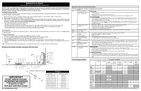
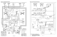
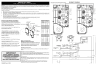
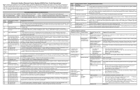
SERVICE DATA SHEET Electric Ranges with ESEC20 and Induction Smooothop NOTICE - This service data sheet is intended for use by persons having electrical and mechanical training and a level of knowledge of these subjects generally considered acceptable in the appliance repair trade. The manufacturer cannot be responsible, nor assume any liability for injury or damage of any kind arising from the use of this data sheet. SAFE SERVICING PRACTICES To avoid the possibility of personal injury and/or property damage, it is important that safe servicing practices be observed. The following are examples, but without limitation, of such practices. 1. Before servicing or moving an appliance remove power cord from electrical outlet, trip circuit breaker to OFF, or remove fuse. 2. Never interfere with the proper installation of any safety device. 3. GROUNDING: The standard color coding for safety ground wires is GREEN or GREEN WITH YELLOW STRIPES. Ground leads are not to be used as current carrying conductors. It is extremely important that the service technician reestablish all safety grounds prior to completion of service. Failure to do so will create a potential safety hazard. 4. Prior to returning the product to service, ensure that: • All electric connections are correct and secure. • All electrical leads are properly dressed and secured away from sharp edges, high-temperature components, and moving parts. • All uninsulated electrical terminals, connectors, heaters, etc. are adequately spaced away from all metal parts and panels. • All safety grounds (both internal and external) are correctly and securely reassembled. Electronic Surface Element Control (ESEC) This range is equipped with an Electronic Surface Element Control (ESEC), which precisely controls the smoothtop elements LR POTENTIOMETER/ DISPLAY BOARD at multiple settings. The warmer zone is not controlled by the ESEC. For the user, the elements are operated by pushing in and turning the knobs to the desired settings. The control settings are LF POTENTIOMETER/ DISPLAY BOARD shown in 2-digit displays above each knob. ELECTRONIC OVEN CONTROL (EOC) RR POTENTIOMETER/ DISPLAY BOARD Hot Surface display message (HE) - If any of the induction elements are hot, the hot surface message "HE" will display and remain ON until the cooktop cools. RF POTENTIOMETER/ DISPLAY BOARD ESEC lockout feature (--) - The electronic oven control's self-clean and Cooktop Lockout features will not operate when a surface element is ON. Conversely, the surface elements controlled by the ESEC will not operate when an oven control self-clean or Cooktop Lockout mode is active. When the oven control is in a self-clean or Cooktop Lockout mode, "--" will appear in the ESEC displays to signify that the surface heating elements are locked out. USER INTERFACE BOARD (UIB) INDUCTION CONTROL ASSEMBLY Displayed Power Level Lo 1.5 2.0 2.5 3.0 3.5 4.0 4.5 5.0 5.5 6.0 6.5 Power Level % 3.0 4.25 5.5 7.5 10.5 13.0 15.5 18.0 21.0 25.0 31.0 38.0 ESEC system components The ESEC system consists of the following components: UIB or User Interface Board - this circuit board is mounted with screws and stand-offs in the backguard. Potentiometer display boards - push-to-turn controls and cooktop displays for each element and connections to the UIB. ESEC harness connects the ESEC system components and communicates with the EOC (Electronic Oven Control). Induction control assembly - circuit boards in plastic housings mounted on the range back side, on two brackets with four screws. Notes on replacing parts Replacing an induction control assembly* When replacing an induction control assembly on the back of the range, do not over-tighten the 2 screws that secure each Control Assembly to the range or the screws that secure the rear wire shield to the Control Assembly. Over-tightening the screws can damage the plastic housings holding the circuit boards. 7.0 45.0 7.5 50.0 8.0 54.0 8.5 59.0 9.0 64.0 9.5 80.0 Hi 100 Pb 125-141 Replacing an induction element Whenever replacing any induction element use only the screws supplied with the range to secure the element to the mounting panel. Never use any other type of screw to attach the induction element . IMPORTANT DO NOT REMOVE THIS BAG OR DESTROY THE CONTENTS WIRING DIAGRAMS AND SERVICE INFORMATION ENCLOSED REPLACE CONTENTS IN BAG 316904473 Rev A (1303) Replacing the potentiometer/display boards* Each of the four push-to-turn controls (potentiometer/display boards) are mounted to the control panel with a hex nut and lockwasher. When replacing a potentiometer, do not over-tighten the hex nut - a torque of only 8 in-lb is required to properly mount the potentiometer. NOTE: Both potentiometer/display boards must be replaced in pairs (LH or RH sides) at the same time. Replacing the UIB* When replacing the UIB in the backguard, DO NOT over tighten the screws that secure the UIB. To secure the UIB use NO MORE THAN 20 in. - lbs. Over tightening these screws can possibly damage the UIB board. * Please note: Electronic boards are very sensitive to static electricity. Static electricity can permanently damage electronic boards. Before handling these parts, be sure to drain static electricity from your body by properly grounding yourself. Induction Controls Wiring/Connections ESEC with Induction Cooktop SCHEMATIC DIAGRAM
-
 1
1 -
 2
2 -
 3
3 -
 4
4
 |
 |
