Frigidaire FPBM189KF Installation Instructions (All Languages) - Page 5
C Vertical Exhaust - installation instructions
 |
UPC - 012505560262
View all Frigidaire FPBM189KF manuals
Add to My Manuals
Save this manual to your list of manuals |
Page 5 highlights
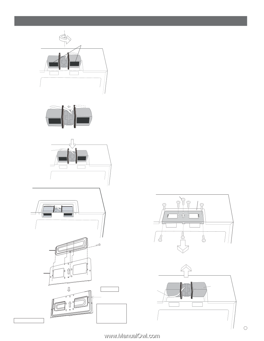
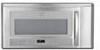
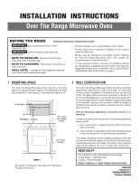
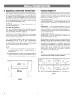
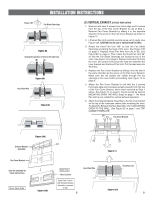
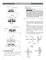
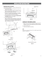
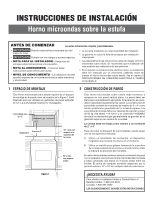
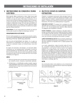
INSTALLATION INSTRUCTIONS Rotate 180° Fan Blade Openings Figure 9A Change the position of wire to left side hole (B) (A) Figure 9B Hood Fan Wire Figure 9C (C) VERTICAL EXHAUST: OUTSIDE VENTILATION 1. Remove and save 3 screws from back edge and 5 screws from the top of the Fan Cover Bracket to use at Step 5. Remove Fan Cover Bracket by sliding it in the opposite direction of the arrow on the Fan Cover Bracket as shown in Figure 11. 2. Lift Hood Fan Unit carefully and slip wires out of cavity. See Figure 12A. CAUTION: Do not pull or stretch Hood Fan Wire. 3. Rotate the Hood Fan Unit 180° so that the Fan Blade Openings are facing the back of the oven. See Figure 12B on page 6. Replace Hood Fan Wire from (A) to (B). See Figure12C on page 6. Then rotate the Hood Fan Unit 90° so that the Fan Blade Openings are facing the top of the oven. See Figure 13 on page 6. Replace Hood Fan Unit into the oven. Be careful not to pinch the lead wire between the inner bracket and the Hood Fan Unit. Put the lead wire into Wire Box. 4. Replace the Fan Cover Bracket by sliding it into the slits in the same direction as the arrow on the Fan Cover Bracket. Make sure the fan blades are visible through the top openings in the oven before proceeding. See Figure 14 on page 6. 5. Attach the Fan Cover Bracket to unit with the 3 screws from back edge and 4 screws except screw(A) from the top of the Fan Cover Bracket, which were removed at Step 1 above. See Figure 14 on page 6. Screw (A) will be used at MOUNTING OVEN THE WALL Step5 on page 7. The Hood Fan Unit is now rotated for vertical exhaust operation. 6. Attach the Exhaust Damper Assembly to the fan cover bracket on the top of the outercase cabinet after mounting the oven. To attach the Exhaust Damper Assembly, refer to MOUNTING OVEN TO THE WALL, See Figure 20 on page 7 and TOP CABINET TEMPLATE. (A) Fan Cover Bracket Figure 10A Exhaust Damper Assembly Fan Cover Bracket Save the assembly for future instructions. Oven Rear Side Figure 10B Wall Side Rear Cushion Apply Rear Cushion after Exhaust Damper Assembly is screwed to wall. 5 Hood Fan Wire Figure 11 Hood Fan Unit Figure 12A E
-
 1
1 -
 2
2 -
 3
3 -
 4
4 -
 5
5 -
 6
6 -
 7
7 -
 8
8 -
 9
9 -
 10
10 -
 11
11 -
12
-
13
-
14
-
15
-
16
-
17
-
18
-
19
-
20
-
21
-
22
-
23
-
24
 |
 |