Frigidaire FPIC3677RF Wiring Diagram
Frigidaire FPIC3677RF Manual
 |
View all Frigidaire FPIC3677RF manuals
Add to My Manuals
Save this manual to your list of manuals |
Frigidaire FPIC3677RF manual content summary:
- Frigidaire FPIC3677RF | Wiring Diagram - Page 1
INDUCTION COOKTOP NOTICE - This service servicing or moving an appliance remove power cord from electrical outlet, trip circuit breaker to OFF, or remove fuse. 2. Never interfere with the proper installation damage electronic boards. Before handling these parts, be sure to drain static electricity - Frigidaire FPIC3677RF | Wiring Diagram - Page 2
error. 2. Has the appliance been recently serviced? If so, verify the part numbers of the replaced components. Incorrect replacement parts will cause software errors. 3. If parts check correctly and the problem persists, replace the induction board indicated by the error code. 4. If - Frigidaire FPIC3677RF | Wiring Diagram - Page 3
robinet d'alimentation en gaz. 2. N'entravez jamais l'installation adéquate de tout dispositif de sécurité. 3. MISE la terre de sécurité avant de terminer le service. Si cette recommandation n'est pas suivie à la d'un élément à induction Pour remplacer un élément à induction, n'utilisez que les - Frigidaire FPIC3677RF | Wiring Diagram - Page 4
de puissance de la table de cuisson à induction sont défectueux. 1. Vérifiez que le capteur est installé correctement. Mesurez environ 100 KOhms pour la positionné et qu'il touche la vitre. 1. Suivez les instructions comment toucher correctement le contrôleur. 2. Remplacez panneau d'interface de
-
 1
1 -
 2
2 -
 3
3 -
 4
4
 |
 |
NOTICE - This service data sheet is intended for use by persons having electrical
and mechanical training and a level of knowledge of these subjects generally
considered acceptable in the appliance repair trade. The manufacturer cannot
be responsible, nor assume any liability for injury or damage of any kind arising
from the use of this data sheet.
SAFE SERVICING PRACTICES
To avoid the possibility of personal injury and/or property damage, it is important
that safe servicing practices be observed. The following are examples, but without
limitation, of such practices.
1. Before servicing or moving an appliance remove power cord from electrical outlet,
trip circuit breaker to OFF, or remove fuse.
2. Never interfere with the proper installation of any safety device.
IMPORTANT
DO NOT REMOVE THIS BAG
OR DESTROY THE CONTENTS
WIRING DIAGRAMS AND SERVICE
INFORMATION
ENCLOSED
REPLACE CONTENTS IN BAG
p/n A00498604 Rev B (1603)
3. GROUNDING: The standard color coding for safety ground wires is GREEN or
GREEN WITH YELLOW STRIPES. Ground leads are not to be used as current
carrying conductors.
It is extremely important that the service technician
reestablish all safety grounds prior to completion of service. Failure to do
so will create a potential safety hazard.
4.
Prior to returning the product to service, ensure that:
• All electric connections are correct and secure.
• All electrical leads are properly dressed and secured away from sharp edges,
high-temperature components, and moving parts.
• All uninsulated electrical terminals, connectors, heaters, etc. are adequately
spaced away from all metal parts and panels.
• All safety grounds (both internal and external) are correctly and securely
reassembled.
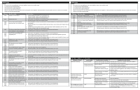
Indicated
% Power
Notes
0
0
Off
Lo
7
Keep Warm
1.5
9
-
2
12
-
2.5
15
-
3
17
-
3.5
18
-
4
19
-
4.5
20
-
5
21
-
5.5
25
-
6
31
-
6.5
38
-
7
45
-
7.5
50
8
54
-
8.5
59
9
64
-
9.5
80
Hi
100
Pb
138-152
PowerBoost
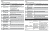
Electronic Surface Element Control (ESEC)
This cooktop is equipped with an Electronic Surface Element
Control (ESEC), which precisely controls the smoothtop cooking
elements at multiple settings. For the user, the elements are
operated by the knobs. The control settings are shown in 2-digit
displays.
Hot Surface display message
- If any of the induction elements
are hot, the hot surface message (HE) will display and remain
ON until the cooktop cools.
Replacing an induction element
Whenever replacing any induction element use only the screws
supplied with the range to secure the element to the mounting
panel. Never use any other type of screw to attach the induction
element.
* Please note:
Electronic boards are very sensitive to static
electricity. Static electricity can permanently damage electronic
boards. Before handling these parts, be sure to drain static elec-
tricity from your body by properly grounding yourself.
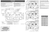
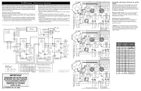
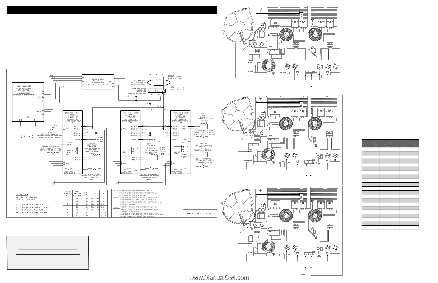
BC3
TO USER INTERFACE BOARD
Á PLAQUETTE D'INTERFACE DE UTILISATEUR
THERMAL CUT-OUT
COUPE-CIRCUIT THERMIQUE
GENERATOR/POWERBOARD-LEFT (1)
CARTE GENERATEUR-GAUCHE (1)
GENERATOR/POWERBOARD-CENTER (2)
CARTE GENERATEUR-CENTRE (2)
BC3
B81
BC4
B71
TAB1
TAB2
BC1
TAB102
TAB101
BC5
BPL1
BPL2
BPN2
BPN1
BPE03
BC3
B81
BC4
B71
TAB1
TAB2
BC1
TAB102
TAB101
BC5
BPL1
BPL2
BPN2
BPN1
BPE03
THERMAL CUT-OUT
COUPE-CIRCUIT THERMIQUE
THERMAL CUT-OUT
COUPE-CIRCUIT THERMIQUE
GENERATOR/POWERBOARD-RIGHT (3)
CARTE GENERATEUR-DROIT (3)
BC3
B81
BC4
B71
TAB1
TAB2
BC1
TAB102
TAB101
BC5
BPL1
BPL2
BPN2
BPN1
BPE03
ID JUMPER: ADDRESS 1
DO NOT CONNECT
BC1
IDENTIFICATEUR: ADRESSE 2
NE PAS BRANCHER
BC1
ID JUMPER: ADDRESS 2 DO NOT
CON-
NECT BLACK JUMPER TO
BC5 OR BC1
IDENTIFICATEUR: ADRESSE 2
NE PAS BRANCHEZ EN UTILISANT
FAISCEAU-FIL NOIR
BC5 OU BC1
ID JUMPER: ADDRESS 3
CONNECT RED JUMPER TO
BC1
IDENTIFICATEUR: ADRESSE 2
BRANCHEZ EN UTILISANT
FAISCEAU-FIL ROUGE
BC1
SERVICE DATA SHEET
36” INDUCTION COOKTOP