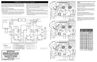
Frigidaire FPIC3677RF Wiring Diagram - Page 2
ADDITIONAL ERROR FAULT CONDITIONS, ERROR CODES, UI Display, Error Description, Corrective Action - cooktop
 |
View all Frigidaire FPIC3677RF manuals
Add to My Manuals
Save this manual to your list of manuals |
Page 2 highlights
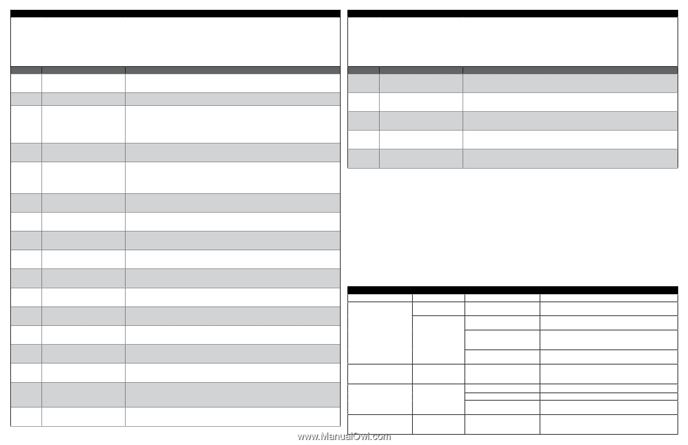
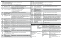
ERROR CODES NOTES: • C0 errors are for errors applicable to the entire appliance and the user interface board. • C1 errors are for the left powerboard. • C2 errors are for the center powerboard. • C3 errors are for the right powerboard. • Make sure all knobs are in the OFF position when cycling power to the appliance. Leaving the knobs in any ON position will result in further error messages and prevent accurate troubleshooting. UI Display C014 C016 C122 C222 C322 C035 C149 C249 C349 C157 C257 C357 C158 C258 C358 C159 C259 C359 C161 C261 C361 C164 C264 C364 C165 C265 C365 C167 C267 C367 C168 C268 C368 C169 C269 C369 C170 C270 C370 C171 C271 C371 C172 C272 C372 Error Description Corrective Action Keyboard, LED tail failure. 1. Confirm cooktop ON indicator LED is connected on J3. 2. If problem persists, replace cooktop ON indicator setup. 3. If problem persists, replace the user interface board. Potentiometer error. 1. Cycle power to the appliance, wait 30 seconds before reconnecting power. 2. If problem persists, replace user interface board. Loss of communication between 1. Check the MACS connection (communication harness) between user interface board and induction powerboard and user interface board. powerboards. 2. If problem persists, check continuity of MACS harness between each control board. Replace harness if defective. 3. If harness is good and problem persists, replace the induction board indicated by the error code. 4. If problem persists, replace the user interface board. ON indicator display failure: the displays 1. Cycle power to the appliance, wait 30 seconds before reconnecting power. cannot display the LEDs properly, the 2. If problem persists, replace user interface board. mechanism for the displays has failed. Induction powerboard configuration 1. Cycle power to the appliance, wait 30 seconds before reconnecting power. compatibility error. 2. Has the appliance been recently serviced? If so, verify the part numbers of the replaced components. Incorrect replacement parts will cause software errors. 3. If parts check correctly and the problem persists, replace the induction board indicated by the error code. 4. If problem persists, replace the user interface board. MAINS (power supply) relay stuck on 1. Cycle power to the appliance, wait 30 seconds before reconnecting power. induction powerboard. 2. If problem persists, replace the induction board indicated by the error code. 400v detection error on induction powerboard. 1. Cycle power to the appliance, wait 30 seconds before reconnecting power. 2. If problem persists, replace the induction board indicated by the error code. Too low MAINS (power supply) voltage 1. Check line voltage coming into the appliance. detected on induction powerboard. 2. If problem persists, replace the induction board indicated by the error code. 15v supply too high or too low in induction powerboard. 1. Cycle power to the appliance, wait 30 seconds before reconnecting power. 2. If problem persists, replace the induction board indicated by the error code. Cooling fan on the induction 1. Check for interference, blockages, debris, dust, or anything else that would physically prevent the fan powerboard is blocked or otherwise from moving. unable to turn. 2. If problem persists, replace the induction board indicated by the error code. Temperature sensor open on induction 1. Check sensor connections on the the induction board indicated by the error code. powerboard. 2. If problem persists, replace the induction board indicated by the error code. Communication loss between control 1. and power microprocessors on 2. induction powerboard. Failure check found inconsistent 1. voltage measurement between the two 2. induction powerboard microprocessors. Failure check found inconsistent 1. current measurement between the two 2. induction powerboard microprocessors. Failure check found inconsistent power 1. frequency detection between the two 2. induction powerboard microprocessors. Failure check found inconsistent power 1. currents between the drive circuit for the 2. coils (IGBT) and the main power current on the induction powerboard. Internal syncing error between the two 1. induction powerboard microprocessors. 2. Cycle power to the appliance, wait 30 seconds before reconnecting power. If problem persists, replace the induction board indicated by the error code. Cycle power to the appliance, wait 30 seconds before reconnecting power. If problem persists, replace the induction board indicated by the error code. Cycle power to the appliance, wait 30 seconds before reconnecting power. If problem persists, replace the induction board indicated by the error code. Cycle power to the appliance, wait 30 seconds before reconnecting power. If problem persists, replace the induction board indicated by the error code. Cycle power to the appliance, wait 30 seconds before reconnecting power. If problem persists, replace the induction board indicated by the error code. Cycle power to the appliance, wait 30 seconds before reconnecting power. If problem persists, replace the induction board indicated by the error code. ERROR CODES NOTES: • C0 errors are for errors applicable to the entire appliance and the user interface board. • C1 errors are for the left powerboard. • C2 errors are for the center powerboard. • C3 errors are for the right powerboard. • Make sure all knobs are in the OFF position when cycling power to the appliance. Leaving the knobs in any ON position will result in further error messages and prevent accurate troubleshooting. UI Display C173 C273 C373 C174 C274 C374 C175 C275 C375 C180 C280 C380 C181 C281 C381 Error Description Failure check found too-high temperature on induction power board. Corrective Action 1. Cycle power to the appliance, wait 30 seconds before reconnecting power. 2. If problem persists, replace the induction board indicated by the error code. Drive circuit for the coils and/or the heat 1. sink for the induction power boards has 2. a failure. Failure check found a bad sensor 1. or a shorted circuit on the induction 2. powerboard. Power supply and/or frequency lost on 1. the induction powerboard. 2. Check that the sensor is installed correctly, measure approximately 100K Ohm for NTC.. If problem persists, replace the induction board indicated by the error code. Check the sensor connections on the induction board indicated by the error code. If problem persists, replace the induction board indicated by the error code. Cycle power to the appliance, wait 30 seconds before reconnecting power. If problem persists, replace the induction board indicated by the error code. Cooling fan not connected on the induction powerboard. 1. Check cooling fan connections on the induction board indicated by the error code. 2. If problem persists, replace the induction board indicated by the error code. ADDITIONAL ERROR (FAULT) CONDITIONS Symptom or failure Control Display Pan does not heat up. Normal operation. Flashing "Power level" and pan does not heat. Individual cooking zones cannot be used or cannot always be used. Cooking power too low or shuts down prematurely. None. Normal operation HE in display when cooking "HE" zone is cold and switched off. Possible cause or condition Pan too small for proper pan detection and only works with low power. Pan not detected. Induction coil not correctly connected or induction coil open. Distance between coil and glass ceramic too large. Test cables & connections. User interface defective. Suggested Corrective Action Use larger pan or this pan on a smaller cooking zone. Refer to owners guide for proper pan selection. Check whether the pots or pans are suitable for induction. Refer to owners guide for proper pan selection. Check the coil wire terminal connections. Ensure that they are properly connected and tightened. Test continuity of coil (should be less than 1 ohm). Check whether the coil is properly positioned and touching the glass cooktop surface. 1. Follow instructions for proper use of touch controls. 2. Replace user interface. Ventilation slots obstructed. Unsuitable pots ( bottom bent). Distance between coil and glass ceramic too large. Temperature sensor defect. Clear vent openings. Follow owners guide for proper pan selection. Check whether the glass ceramic was pushed down when being screwed in position and the coil has been correctly positioned. 1. Test coil sensor , approximately 100K ohms at room temperature. Replace coil if resistance is incorrect. 2. Replace power generator board.
-
 1
1 -
 2
2 -
 3
3 -
 4
4
 |
 |