Frigidaire GLMB209DS Installation Instructions - Page 2
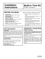
Installation Instructions
 |
View all Frigidaire GLMB209DS manuals
Add to My Manuals
Save this manual to your list of manuals |
Page 2 highlights
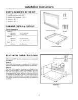
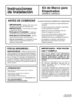
Installation Instructions PARTS INCLUDED IN THE KIT 1. Front Frame Assembly - QTY 1 2. Exhaust Duct Assembly - QTY 1 3. Screw A - QTY 2 4. Screw B - QTY 4 Screw A CABINET OR WALL CUTOUT Cutout Dimensions Height (A) Minimum Maximum Width (B) Minimum Maximum Depth (C) Minimum 16 3/4" (42.5 cm) 17" (43.2 cm) 24 3/8" (61.9 cm) 24 11/16" (62.7 cm) 20" (50.8 cm) Front Frame Assembly Screw B Exhaust Duct Assembly ELECTRICAL OUTLET LOCATION Outlet should NOT be in the shaded area as indicated on Illustration 1 NOTE 1: If the Depth (C) dimension is greater than 21" (53.3 cm), the outlet location may be in any area on the rear wall. NOTE 2: The floor of the opening should be constructed of ply- wood strong enough to suppor t the weight of the oven and floor load (approximately 100 pounds). The floor A should be level for proper operation of the oven. Be sure to check the local building code as it may require that the opening be enclosed with side, ceiling and rear partition. The proper functioning of the oven does not require the enclosure. 4" (10.2 cm) 6" (15.2 cm) (10.24"cm) B C Illustration 1 2
-
 1
1 -
 2
2 -
 3
3 -
 4
4 -
 5
5 -
 6
6 -
 7
7 -
 8
8 -
9
-
10
-
11
-
12
 |
 |
