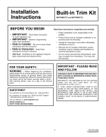
Frigidaire GLMB209DS Installation Instructions - Page 3
Exhaust Duct Assembly, Frame Installation
 |
View all Frigidaire GLMB209DS manuals
Add to My Manuals
Save this manual to your list of manuals |
Page 3 highlights
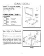
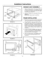
Installation Instructions Flanges Screw A Exhaust Duct Assembly Screw A Illustration 2 EXHAUST DUCT ASSEMBLY 1. Place the Exhaust Duct in the opening. When the Exhaust Duct Assembly is in the opening correctly, the flanges will be tightly against the lower edge of the opening. See Illustration 2. 2. Secure the Exhaust Duct Assembly with the two screws A. IMPORTANT: Secure screws in outer hole. FRAME INSTALLATION 1. Place the oven adjacent to the wall or cabinet opening. Plug the power cord into the electrical outlet. 2. Carefully guide the assembled oven into the prepared opening. Slide the oven on the Exhaust Duct Assembly. See Illustration 3. Avoid pinching the cord between the oven and the wall. Adjust the position of the oven so that the feet of the oven are fitted into the recesses of the Exhaust Duct Assembly. See Illustration 4. 3. Position the FRAME ASSEMBLY to be square with the oven. Carefully place the FRAME ASSEMBLY on the oven. Check that it is level and then secure with two SCREWS B. See Illustration 5. 4. Secure the bottom portion of the FRAME ASSEMBLY with the two remaining SCREWS B. See Illustration 5. Illustration 3 Foot Screw B Screw B Screw B Exhaust Duct Assembly Recess Illustration 4 3 Screw B Illustration 5
-
 1
1 -
 2
2 -
 3
3 -
 4
4 -
 5
5 -
 6
6 -
 7
7 -
 8
8 -
 9
9 -
10
-
11
-
12
 |
 |
