Fujitsu A9Z111E1014A2001 User Manual - Page 63
Removing a cover, Removing memory modules, Removing and installing components during servicing
 |
View all Fujitsu A9Z111E1014A2001 manuals
Add to My Manuals
Save this manual to your list of manuals |
Page 63 highlights
Removing a cover Removing and installing components during servicing 1 2 ► Remove the screw (1). Keep the screws in a safe place. If you are removing more than one component at the same time, store the screws for the individual components separate from each other. If you install the wrong screws, components may be damaged. ► Lift the cover off the notebook (2). Removing memory modules 3 2 1 ► Carefully push the two mounting clips outwards (1). Memory emxopdaunlseion The memory module snaps upwards (2). ► Pull the memory module out of its slot in the direction of the arrow (3). 1 Fujitsu Technology Solutions 59
-
 1
1 -
2
-
3
-
4
-
5
-
6
-
7
-
8
-
9
-
10
-
11
-
12
-
13
-
14
-
15
-
16
-
17
-
18
-
19
-
20
-
21
-
22
-
23
-
24
-
25
-
26
-
27
-
28
-
29
-
30
-
31
-
32
-
33
-
34
-
35
-
36
-
37
-
38
-
39
-
40
-
41
-
42
-
43
-
44
-
45
-
46
-
47
-
48
-
49
-
50
-
51
-
52
-
53
-
54
-
55
-
56
-
57
-
 58
58 -
 59
59 -
 60
60 -
 61
61 -
 62
62 -
 63
63 -
 64
64 -
 65
65 -
 66
66 -
 67
67 -
 68
68 -
69
-
70
-
71
-
72
-
73
-
74
-
75
-
76
-
77
-
78
-
79
-
80
-
81
-
82
-
83
-
84
-
85
-
86
-
87
-
88
-
89
-
90
-
91
 |
 |

Removing and installing components during servicing
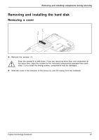
Removing a cover
1
2
►
Remove the screw (1).
Keep the screws in a safe place. If you are removing more than one component at
the same time, store the screws for the individual components separate from each
other. If you install the wrong screws, components may be damaged.
►
Lift the cover off the notebook (2).
Removing memory modules
3
2
1
1
►
Carefully push the two mounting
clips outwards (1).
The memory module snaps upwards (2).
►
Pull the memory module out of its slot
in the direction of the arrow (3).
Fujitsu Technology Solutions
59