Fujitsu MHV2040AT Manual/User Guide - Page 30
Spare Parts, 2.2 Disk Drive Removal, Removal and Replacement Procedure - 40gb
 |
UPC - 683728090210
View all Fujitsu MHV2040AT manuals
Add to My Manuals
Save this manual to your list of manuals |
Page 30 highlights
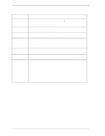
Removal and Replacement Procedure 2.1 Spare Parts See Table 2.1 for the model and parts numbers to order the replacement disk drive. Table 2.1 Model and parts numbers Model Name MHV2120AT MHV2100AT MHV2080AT MHV2060AT MHV2040AT Capacity (user area) 120GB 100GB 80GB 60GB 40GB Mounting screw Order No. M3 Depth 3 M3 Depth 3 M3 Depth 3 M3 Depth 3 M3 Depth 3 CA06557-B042 CA06557-B040/B140 CA06557-B038/B138/B148 CA06557-B026/B126/B136 CA06557-B124 2.2 Disk Drive Removal The method and procedures to demount the disk drive to check the jumper terminal, change the jumper position, or replace the device differ depend on the system cabinet structure. Therefore, for actual working procedures, the specific conditions necessary for each system must be determined. The general removal procedures, with notes, are as follows. a) Disconnect the power-interface cable. b) Remove the screws that attach the drive and remove the drive from the system cabinet. c) When storing or transporting the drive, pack it an antistatic bag in compliance with section 1.1.2 (5) d. and (5) e.. To protect the device from damage and prevent the worker getting hurt, observe the following cautions and precautions in Subsection 1.1.1. Damage or Device damage 1. Perform any removal after the system power is completely disconnected. The cable must not be disconnected and the screws that attach the drive must not be removed with the power ON. 2. Do not move the drive and attach or detach the connector until it comes to a complete stop (about 30 s after the power is turned OFF). 3. Perform the human body grounding to discharge any static electricity from your body (Be sure to wear a wrist strap). 2-2 C141-F072
-
 1
1 -
2
-
3
-
4
-
5
-
6
-
7
-
8
-
9
-
10
-
11
-
12
-
13
-
14
-
15
-
16
-
17
-
18
-
19
-
20
-
21
-
22
-
23
-
24
-
 25
25 -
 26
26 -
 27
27 -
 28
28 -
 29
29 -
 30
30 -
 31
31 -
 32
32 -
 33
33 -
 34
34 -
 35
35 -
36
-
37
-
38
-
39
-
40
 |
 |
