Garmin GHP 12 Autopilot System Installation Instructions - Page 12
Connecting the Devices to a NMEA 2000, Network
 |
View all Garmin GHP 12 Autopilot System manuals
Add to My Manuals
Save this manual to your list of manuals |
Page 12 highlights
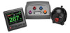
14. Snap the decorative bezel ➊ into place. Connecting the GHC 20 to an Existing NMEA 2000 Network 1. Determine where to connect the GHC 20 ➊ to your existing NMEA 2000 backbone ➋. ➊ ➊ Connecting the GHC 20 For the autopilot system to function correctly, you must connect two wires from the GHC 20 data cable (yellow and black). 1. Connect the yellow wire from the GHC 20 data cable to the yellow wire from the CCU/ECU interconnect cable. If the cable is not long enough, extend the yellow wire with 22 AWG (.33 mm2) wire. 2. Connect the black wire from the GHC 20 data cable to the same ground location as the ECU. If the cable is not long enough, extend the black wire with 22 AWG (.33 mm2) wire. 3. Solder and cover all bare-wire connections. Multiple GHC 20 Considerations You can install multiple GHC 20 devices (sold separately) to control the autopilot from different locations on the boat. • All additional GHC 20 devices must be connected to the NMEA 2000 network (page 12). • To use an additional GHC 20 to turn on the autopilot, connect the yellow and black wires from the additional GHC 20 to the same wires as the primary GHC 20. ◦◦ If you connect additional GHC 20 devices to turn on the autopilot, you must turn them all off to turn off the autopilot. ◦◦ If you do not connect an additional GHC 20 to turn on the autopilot, then the additional GHC 20 will enter standby mode when you turn it off, and the autopilot will remain on until turned off by the primary GHC 20. Connecting the Devices to a NMEA 2000 Network Notice If you have an existing NMEA 2000 network on your boat, it should already be connected to power. Do not connect the included NMEA 2000 power cable to an existing NMEA 2000 network, because only one power source should be connected to a NMEA 2000 network. You can connect the GHC 20 to the CCU through an existing NMEA 2000 network. If you do not have an existing NMEA 2000 network on your boat, all the parts needed to build one are supplied in the GHP 12 package (page 13). Optionally, you can connect NMEA 2000-compatible devices, such as a wind sensor, a water-speed sensor, or a GPS device, to your NMEA 2000 network to use the advanced features of the GHP 12. For more information on NMEA 2000, go to www.garmin.com. ➍ ➌ ➋ 2. Disconnect one side of a NMEA 2000 T-connector from the network. 3. If necessary, to extend the NMEA 2000 network backbone, connect a NMEA 2000 backbone extension cable (not included) to the side of the disconnected T-connector. 4. Add the included T‑connector ➌ for the GHC 20 to the NMEA 2000 backbone by connecting it to the side of the disconnected T‑connector or backbone extension cable. 5. Route the included drop cable ➍ to the bottom of the T-connector added in step 4, and connect it to the T-connector. If the included drop cable is not long enough, you can use a drop cable up to 20 ft. (6 m) long (not included). 6. Connect the drop cable to the to the GHC 20. 7. Connect the drop cable to the T-connector you added in step 3, and to the GHC 20. NOTE: In order for the autopilot to turn on, the yellow wire from the GHC 20 data cable be connected to the yellow wire from the CCU/ECU Interconnect cable, and the black wire from the GHC 20 data cable must be connected to the same ground as the ECU (page 12). 12 GHP 12 Installation Instructions
-
 1
1 -
2
-
3
-
4
-
5
-
6
-
 7
7 -
 8
8 -
 9
9 -
 10
10 -
 11
11 -
 12
12 -
 13
13 -
 14
14 -
 15
15 -
 16
16 -
 17
17 -
18
-
19
-
20
-
21
-
22
-
23
-
24
-
25
-
26
-
27
-
28
-
29
-
30
-
31
-
32
 |
 |
