Garmin GHP Reactor Steer-by-wire Corepack for Viking VIPER Installation Instru - Page 2
Installation Procedures
 |
View all Garmin GHP Reactor Steer-by-wire Corepack for Viking VIPER manuals
Add to My Manuals
Save this manual to your list of manuals |
Page 2 highlights
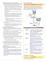
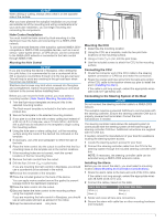
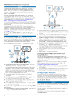
CCU Mounting and Connection Considerations • The CCU is the primary sensor of the GHP Reactor Steer-by- Wire autopilot system. For best performance, observe these considerations when selecting a mounting location. ◦ A handheld compass should be used to test for magnetic interference in the area where the CCU is to be mounted. If the needle on a handheld compass moves when you hold it where you intend to mount the CCU, magnetic interference is present. You must choose another location and test again. ◦ The CCU should be mounted on a rigid surface for best performance. ◦ Although the CCU can be installed in any orientation on your boat, you can avoid the step of defining north in the setup procedure by meeting all of these considerations when selecting a mounting location (optional). ◦ The connectors on the CCU must point toward the bow. ◦ The base of the CCU must be at a right angle to the roll and pitch axis of the boat. ◦ The CCU must be located near the center of rotation of the boat, slightly toward the front, if necessary. • The CCU cable connects the CCU to the steering system and is 3 m (9 ft.) long. ◦ If the CCU cannot be mounted within 3 m (9 ft.) of the steering system, extension cables are available from your local Garmin dealer or at www.garmin.com. ◦ This cable must not be cut. Finding the Best Mounting Location 1 Create a list of all suitable mounting locations for the CCU where no iron, magnets, or high-current wires are located within 60 cm (2 ft.). A large magnet, such as a subwoofer-speaker magnet should be no closer than 1.5 m (5 ft.) to these locations. 2 Locate the center of rotation of the boat, and measure the distance between the center of rotation and each of the suitable mounting locations you listed in step 1. 3 Select the location closest to the center of rotation. If more than one location is approximately the same distance from the center of rotation, you should select the location that best meets these considerations. • The best location is closest to the centerline of the boat. • The best location is lower in the boat. • The best location is slightly forward in the boat. Alarm Mounting and Connection Considerations • The alarm should be mounted near the primary helm station. • The alarm can be mounted under the dashboard. • If needed, the alarm wires can be extended with 28 AWG (0.08 mm2) wire. NMEA 2000 Connection Considerations • The CCU and the helm control must connect to a NMEA 2000 network. • If your boat does not already have a NMEA 2000 network, one can be built using the included NMEA 2000 cables and connectors (Building a Basic NMEA 2000 Network for the Autopilot System). • To use the advanced features of the autopilot, optional NMEA 2000 devices, such as a wind sensor, a water-speed sensor, or a GPS device, can be connected to the NMEA 2000 network. Power and Data Layout WARNING When connecting the power cable, do not remove the in-line fuse holder. To prevent the possibility of injury or product damage caused by fire or overheating, the appropriate fuse must be in place as indicated in the product specifications. In addition, connecting the power cable without the appropriate fuse in place will void the product warranty. Item Description Helm control À Helm control Á data cable NMEA 2000 Â power cable NMEA 2000 Ã network CCU Ä Engine Å connection Alarm Æ Important Considerations This cable should be installed only if you are connecting the autopilot to optional NMEA 0183 devices, such as a wind sensor, a water-speed sensor, or a GPS device (NMEA 0183 Connection Considerations). This cable should be installed only if you are building a NMEA 2000 network. Do not install this cable if there is an existing NMEA 2000 network on your boat. The NMEA 2000 power cable must be connected to a 9 to 16 Vdc power source. The helm control and the CCU must be connected to a NMEA 2000 network using the included T-connectors (NMEA 2000 Connection Considerations). If there is not an existing NMEA 2000 network on your boat, you can build one using the supplied cables and connectors (Building a Basic NMEA 2000 Network for the Autopilot System). The CCU can be mounted in a non-submerged location near the center of the boat, in any orientation (CCU Mounting and Connection Considerations). The CCU must be located away from sources of magnetic interference. The CCU connects either to the engine control directly or through an adapter. Additional instructions are provided with the adapter, if applicable. The alarm provides audible alerts from the autopilot system, and should be installed near the helm control (Installing the Alarm). Installation Procedures CAUTION Always wear safety goggles, ear protection, and a dust mask when drilling, cutting, or sanding. 2
-
 1
1 -
 2
2 -
 3
3 -
 4
4 -
 5
5 -
 6
6 -
 7
7 -
 8
8 -
9
-
10
 |
 |
