Garmin GPSMAP 2206 GPSMAP 2206/2210 Installation Instructions
Garmin GPSMAP 2206 - Marine GPS Receiver Manual
 |
UPC - 753759053024
View all Garmin GPSMAP 2206 manuals
Add to My Manuals
Save this manual to your list of manuals |
Garmin GPSMAP 2206 manual content summary:
- Garmin GPSMAP 2206 | GPSMAP 2206/2210 Installation Instructions - Page 1
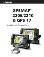
GPSMAP® 2206/2210 & GPS 17 installation instructions Graphic to be replaced - Garmin GPSMAP 2206 | GPSMAP 2206/2210 Installation Instructions - Page 2
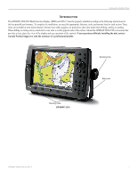
Garmin Web site (www.garmin.com) for current updates and supplemental information concerning the use and operation of this and other Garmin products. Garmin®, GPS service. To obtain warranty service, contact your local Garmin authorized dealer or call Garmin Product Support for shipping instructions - Garmin GPSMAP 2206 | GPSMAP 2206/2210 Installation Instructions - Page 3
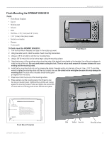
provides a clear, glare-free view of the display and easy operation of the controls. If you experience difficulty installing the unit, contact Garmin Product Support or seek the assistance of a professional installer. Mounting knob Bail mount Mounting holes GPSMAP 2210 GPSMAP 2206/2210 & GPS 17 1 - Garmin GPSMAP 2206 | GPSMAP 2206/2210 Installation Instructions - Page 4
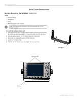
INSTALLATION INSTRUCTIONS INSTALLATION INSTRUCTIONS Surface Mounting the GPSMAP 2206/2210 Tools • Drill and drill bit • Screwdriver • Pencil • Mounting hardware (not included) NOTE: Mounting hardware (fasteners) not included. Mounting holes are 5/16" (7.9 mm) in diameter. To install the bail mount - Garmin GPSMAP 2206 | GPSMAP 2206/2210 Installation Instructions - Page 5
INSTALLATION INSTRUCTIONS Flush Mounting the GPSMAP 2206/2210 Tools • Flush Mount Template • Jig saw • Masking tape • Scissors • Drill • Drill bits-1/8" (3 mm) and 3/8" (6 mm) • 1/16" (2 mm) Allen (Hex) wrench • Sockets or wrenches • Hammer • Center punch To flush mount the GPSMAP 2206/2210: 1. - Garmin GPSMAP 2206 | GPSMAP 2206/2210 Installation Instructions - Page 6
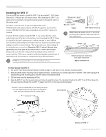
-inch marine mount. When mounting the GPS 17, the cable can be run externally, through the mounting panel, or through the center of the marine mount. The GPS 17 connects to the 18-pin Power/Data Cable on the GPSMAP 2206/2210 and provides the GPS/WAAS signal for the unit. If two or more GPSMAP 2206 - Garmin GPSMAP 2206 | GPSMAP 2206/2210 Installation Instructions - Page 7
cable to pass through. 3. Slide the cable through the mount, and then screw the GPS 17 onto the mount. 4. Fasten the mount to the boat. 5. Route the cable away from sources of electronic interference. Cable run externally Align Notch GPSMAP 2206/2210 & GPS 17 Cable run internally Attaching the - Garmin GPSMAP 2206 | GPSMAP 2206/2210 Installation Instructions - Page 8
and Cables The GPSMAP 2206/2210 comes with an 18-pin Power/Data cable. For some installations, it may be necessary to drill 1.25" (31.7 mm) holes to route the connector end of the cables. Garmin rubber grommets are provided to cover the installation holes (see below). Wiring instructions are found - Garmin GPSMAP 2206 | GPSMAP 2206/2210 Installation Instructions - Page 9
INSTALLATION INSTRUCTIONS CANet Wiring for the GPSMAP 2206/2210 CANet® is a high-speed sonar network. Using the CANet interface optimizes side. ** Fuse size varies based on the unit. See the unit's owner's manual for specific fuse information. CANet COMPATIBLE DEVICE GPSMAP 2206/2210 & GPS 17 7 - Garmin GPSMAP 2206 | GPSMAP 2206/2210 Installation Instructions - Page 10
INSTALLATION INSTRUCTIONS Power/Data Cable Wiring The following pages contain several wiring diagrams. The first diagram on the next page is a simple diagram showing the GPSMAP 2206/2210 MFD using the 18-pin Power/Data wiring harness and the GPS 17. If two GPSMAP 2206/2210 units are installed and - Garmin GPSMAP 2206 | GPSMAP 2206/2210 Installation Instructions - Page 11
INSTALLATION INSTRUCTIONS FUSE 3 A WIRE COLOR RED BLACK ORANGE � GREEN WHITE + - BATTERY 10-33 VOLTS DC GPS 17 GPS/WAAS SENSOR WIRE COLOR RED (POWER) FUSE 1 A BLACK (GROUND) YELLOW (ON) BLUE (DATA IN) � WHITE (DATA OUT) � � GPSMAP 2206/2210 and GPS 17 Basic Wiring - Garmin GPSMAP 2206 | GPSMAP 2206/2210 Installation Instructions - Page 12
INSTALLATION INSTRUCTIONS GPS 17 Optional Alarm Wiring The GPSMAP 2206/2210 has an alarm circuit that can be used with a lamp, a horn, or used to select between visual and audible alerts. + - 100 ma Max Coil Current ���� ���� 10 GPSMAP 2206/2210 & GPS 17 - Garmin GPSMAP 2206 | GPSMAP 2206/2210 Installation Instructions - Page 13
INSTRUCTIONS Final Wiring Connection After all the wiring is complete, plug the 18-pin harness into the center connector on the backside of the GPSMAP 2206 GPSMAP 2206/2210 Owner's Manual for steps on initializing the receiver. 18-pin connector 5-pin CANet connector GPSMAP 2206/2210 & GPS 17 11 - Garmin GPSMAP 2206 | GPSMAP 2206/2210 Installation Instructions - Page 14
INSTALLATION INSTRUCTIONS 12 GPSMAP 2206/2210 & GPS 17 - Garmin GPSMAP 2206 | GPSMAP 2206/2210 Installation Instructions - Page 15
Flush Mount Drilling Template INSTALLATION INSTRUCTIONS Drill using a 11/64" (4.5 mm) drill bit Drill this 3/4" (19 mm) hole if the coax is going to be installed through the mounting panel GPSMAP 2206/2210 & GPS 17 13 - Garmin GPSMAP 2206 | GPSMAP 2206/2210 Installation Instructions - Page 16
. or its subsidiaries Garmin International, Inc. 1200 East 151st Street, Olathe, Kansas 66062, U.S.A. Garmin (Europe) Ltd. Unit 5, The Quadrangle, Abbey Park Industrial Estate, Romsey, SO51 9DL, U.K. Garmin Corporation No. 68, Jangshu 2nd Road, Shijr, Taipei County, Taiwan www.garmin.com Part Number
-
 1
1 -
 2
2 -
 3
3 -
 4
4 -
 5
5 -
 6
6 -
 7
7 -
8
-
9
-
10
-
11
-
12
-
13
-
14
-
15
-
16
 |
 |

GPSMAP
®
2206/2210
& GPS 17
installation instructions
Graphic to be
replaced