Garmin GPSMAP 2206 GPSMAP 2206/2210 Installation Instructions - Page 6
Installing the GPS 17, Mount the GPS 17 at least 3 ft away - marine gps
 |
UPC - 753759053024
View all Garmin GPSMAP 2206 manuals
Add to My Manuals
Save this manual to your list of manuals |
Page 6 highlights
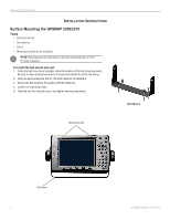
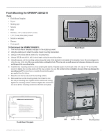
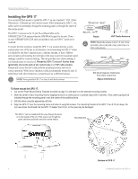
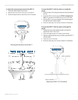
INSTALLATION INSTRUCTIONS Installing the GPS 17 You can install flush mount or install the GPS 17 on any standard 1" O.D. (Outer Dimension), 14 threads-per-inch marine mount. When mounting the GPS 17, the cable can be run externally, through the mounting panel, or through the center of the marine mount. The GPS 17 connects to the 18-pin Power/Data Cable on the GPSMAP 2206/2210 and provides the GPS/WAAS signal for the unit. If two or more GPSMAP 2206/2210 units are installed, only one GPS 17 needs to be installed. To ensure the best reception, mount the GPS 17 in a location that has a clear, unobstructed view of the sky in all directions. Avoid mounting the GPS 17 where it is shaded by the boat's superstructure, a radome antenna, or mast. Sailboat users should avoid mounting the unit high on the mast to prevent inaccurate speed readings caused by excessive heeling. The unit provides more stable readings if it is located nearer to water level. Mount the GPS 17 at least 3 ft away from (preferably above) the path of any radar beam or a VHF radio antenna. Temporarily secure the unit in the preferred mounting location and test for correct operation. With correct operation verified, permanently mount the unit. If interference with other electronics is experienced, try a different location. NOTE: Never paint the GPS 17 or clean it with harsh solvents. ABOVE - BEST Radar BELOW - OK Radar 3' VHF Radio Antenna NOTE: Mount the antenna at least 3 ft away from (preferably above) the path of any radar beam or a VHF radio antenna. EMI BETTER BEST GOOD SS JAYHAWK EMI (Electromagnetic Interference) from engine components Signal Interference To flush mount the GPS 17: 1. Cut out the Flush Mount Drilling Template provided on page 13, and tape it on the selected mounting location. 2. Mark the center of each mounting hole by tapping the end of a center punch or pointed object with a hammer. If the cable is going to be installed through the mounting panel, mark the center of the additional hole. 3. Drill the holes using the appropriate drill bits. 4. Align the GPS 17 over the mounting holes and fasten it using M4 screws. The mounting threads in the GPS 17 are 8.10 mm deep. Do not use screws that thread into the GPS 17 deeper than 8 mm, or the case may be damaged. The GPS 17 can be installed with the coax through the panel or on the outside of the unit. If the coax is run through the panel, seal the outside exit area with marine sealant. Mounting holes Bottom of GPS 17 4 GPSMAP 2206/2210 & GPS 17
-
 1
1 -
 2
2 -
 3
3 -
 4
4 -
 5
5 -
 6
6 -
 7
7 -
 8
8 -
 9
9 -
 10
10 -
 11
11 -
 12
12 -
13
-
14
-
15
-
16
 |
 |
