Garmin GPSMAP 696 Owner's Manual - Page 56
Panel, The Panel shows a graphic Horizontal Situation Indicator HSI surrounded
 |
View all Garmin GPSMAP 696 manuals
Add to My Manuals
Save this manual to your list of manuals |
Page 56 highlights
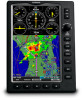
Overview GPS Navigation 2.2 PANEL The panel shows GPS-derived data in a graphical format. Keep in mind the differences between the GPS-derived panel and mechanical instruments, as mechanical panel instruments use sensors that provide information different from that derived using GPS. - Next Waypoint HSI -Distance GPS Navigation Additional Features Hazard Avoidance Flight Planning Ground Speed Altitude Turn Rate Indicator Vertical Speed Estimated Time Enroute Panel (Map Page) CDI Scale The Panel shows a graphic Horizontal Situation Indicator (HSI) surrounded by additional indicators. The graphic HSI depicts the course to the destination or the next waypoint in a flight plan, current ground track, off course error, and a To/From indication. The rotating compass indicates your current ground track at the top of the page. The course pointer and course deviation needle indicate the course and whether you are on the course. The Bug Indicator can be set to 'Bearing' (default), 'Course to Steer', a specific heading reference ('User Selected'), or 'Off'. Bearing is the compass direction from the present position to a destination waypoint. Course to Steer is the recommended direction to steer in order to reduce cross-track error and return to the course line. The Course Deviation Indicator, or needle, indicates how far off course, left or right, based on its placement along the course deviation scale. 40 Garmin GPSMAP 695/696 Owner's Manual 190-00919-00 Rev. G Appendices Index
-
 1
1 -
2
-
3
-
4
-
5
-
6
-
7
-
8
-
9
-
10
-
11
-
12
-
13
-
14
-
15
-
16
-
17
-
18
-
19
-
20
-
21
-
22
-
23
-
24
-
25
-
26
-
27
-
28
-
29
-
30
-
31
-
32
-
33
-
34
-
35
-
36
-
37
-
38
-
39
-
40
-
41
-
42
-
43
-
44
-
45
-
46
-
47
-
48
-
49
-
50
-
 51
51 -
 52
52 -
 53
53 -
 54
54 -
 55
55 -
 56
56 -
 57
57 -
 58
58 -
 59
59 -
 60
60 -
 61
61 -
62
-
63
-
64
-
65
-
66
-
67
-
68
-
69
-
70
-
71
-
72
-
73
-
74
-
75
-
76
-
77
-
78
-
79
-
80
-
81
-
82
-
83
-
84
-
85
-
86
-
87
-
88
-
89
-
90
-
91
-
92
-
93
-
94
-
95
-
96
-
97
-
98
-
99
-
100
-
101
-
102
-
103
-
104
-
105
-
106
-
107
-
108
-
109
-
110
-
111
-
112
-
113
-
114
-
115
-
116
-
117
-
118
-
119
-
120
-
121
-
122
-
123
-
124
-
125
-
126
-
127
-
128
-
129
-
130
-
131
-
132
-
133
-
134
-
135
-
136
-
137
-
138
-
139
-
140
-
141
-
142
-
143
-
144
-
145
-
146
-
147
-
148
-
149
-
150
-
151
-
152
-
153
-
154
-
155
-
156
-
157
-
158
-
159
-
160
-
161
-
162
-
163
-
164
-
165
-
166
-
167
-
168
-
169
-
170
-
171
-
172
-
173
-
174
-
175
-
176
-
177
-
178
-
179
-
180
-
181
-
182
-
183
-
184
-
185
-
186
-
187
-
188
-
189
-
190
-
191
-
192
-
193
-
194
-
195
-
196
-
197
-
198
-
199
-
200
-
201
-
202
-
203
-
204
-
205
-
206
-
207
-
208
-
209
-
210
-
211
-
212
-
213
-
214
-
215
-
216
-
217
-
218
-
219
-
220
-
221
-
222
-
223
-
224
-
225
-
226
-
227
-
228
-
229
-
230
-
231
-
232
-
233
-
234
-
235
-
236
-
237
-
238
-
239
-
240
-
241
-
242
-
243
-
244
-
245
-
246
-
247
-
248
-
249
-
250
-
251
-
252
-
253
-
254
-
255
-
256
-
257
-
258
-
259
-
260
-
261
-
262
-
263
-
264
-
265
-
266
-
267
-
268
-
269
-
270
-
271
-
272
-
273
-
274
-
275
-
276
-
277
-
278
-
279
-
280
 |
 |
