Garmin GPSMAP 8500 Black Box Installation Instructions - Page 10
Lamp or Horn Connections, Video Input and Output Considerations
 |
View all Garmin GPSMAP 8500 Black Box manuals
Add to My Manuals
Save this manual to your list of manuals |
Page 10 highlights
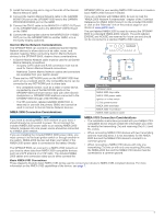
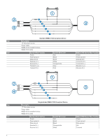
Item  à Description NMEA 0183-compliant device NMEA 0183 cable Item Garmin Wire Function Power Power ground Data ground RxB (-) RxA (+) Lamp or Horn Connections The device can be used with a lamp, a horn, or both, to sound or flash an alert when the chartplotter displays a message. This is optional, and the alarm wire does not need to be used in order for the device to function normally. When connecting the device to a lamp or horn, observe these considerations. • The alarm circuit switches to a low-voltage state when the alarm sounds. Garmin Wire Color Red Black Black Orange/white White NMEA 0183 Device Wire Function Power Power ground Data ground N/A TxA (+) • The maximum current is 100 mA, and a relay is needed to limit the current from the chartplotter to 100 mA. • To manually toggle visual and audible alerts, you can install single-pole, single-throw switches. Item Description 10-35 Vdc power source À Power cable Á Horn  Lamp à NMEA 0183 cable Ä Relay (100 mA coil current) Å Toggle switches to enable and disable lamp or horn alerts Æ Item Ê Ë Ì Wire Color Red Black Yellow Wire Function Power Ground Alarm Video Input and Output Considerations The GPSMAP 8500 allows video input from four composite sources, and video output to two digital or analog displays. When connecting video input and output sources, observe these considerations. • The four composite-video ports are labeled CVBS 1 IN, CVBS 2 IN, CVBS 3 IN, and CVBS 4 IN. ◦ These four ports use BNC connectors. You can use a BNC to RCA adapter to connect a composite-video source with RCA connectors to these ports. 10 ◦ The video from sources connected to these ports is available only for display on the GMM or on an additional monitor connected to the same GPSMAP 8500. Composite video is not shared across the Garmin Marine Network or NMEA 2000 network. • The two DVI-I output ports are labeled MAIN DVI-I VIDEO OUT and MIRROR DVI-I VIDEO OUT. These two ports use DVI-I connectors, and are compatible with a variety of digital and analog connectors and adapters. ◦ You can use a DVI-D cable to connect to a GMM or other DVI-compatible digital display. If needed, you can use a DVI-D to HDMI adapter to connect to an HD TV or other HDMI-compatible display. ◦ You can use a DVI-I cable to connect to a computer monitor or other DVI-I-compatible display. If needed, you can use a DVI-I to VGA adapter to connect to a VGAcompatible display. • The MAIN DVI-I VIDEO OUT port is designed for use with the primary GMM. See page 4 for more information. A thirdparty monitor can be connected to this port, but will not allow for touchscreen interface with the device. • The MIRROR DVI-I VIDEO OUT port allows you to view a mirror image of the MAIN DVI-I VIDEO OUT on a connected display.
-
 1
1 -
2
-
3
-
4
-
 5
5 -
 6
6 -
 7
7 -
 8
8 -
 9
9 -
 10
10 -
 11
11 -
 12
12
 |
 |
