Garmin GPSMAP 8700 Black Box Installation Instructions PDF - Page 2
Connection Considerations
 |
View all Garmin GPSMAP 8700 Black Box manuals
Add to My Manuals
Save this manual to your list of manuals |
Page 2 highlights
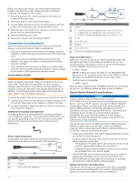
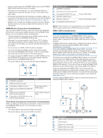
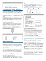
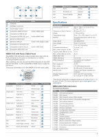
Before you mount the device, you must select a mounting location and determine what screws and other mounting hardware are needed for the surface. 1 Place the device in the mounting location and mark the location of the pilot holes. 2 Drill a pilot hole for one corner of the device. 3 Loosely fasten the device to the mounting surface with one corner and examine the other three pilot-hole marks. 4 Mark new pilot-hole locations if necessary, and remove the device from the mounting surface. 5 Drill the remaining pilot holes. 6 Secure the device to the mounting location. Connection Considerations When connecting this device to power and to other Garmin devices, you should observe these considerations. • The power and ground connections to the battery must be checked to make sure they are secured and cannot become loose. • The cables may be packaged without the locking rings installed. The cables should be routed before the locking rings are installed. • After installing a locking ring on a cable, you should make sure the ring is securely connected and the o-ring is in place so the power or data connection remains secure. Connecting to Power WARNING When connecting the power cable, do not remove the in-line fuse holder. To prevent the possibility of injury or product damage caused by fire or overheating, the appropriate fuse must be in place as indicated in the product specifications. In addition, connecting the power cable without the appropriate fuse in place voids the product warranty. 1 Route the power cable to the power source and to the device. 2 Connect the red wire to the positive (+) battery terminal, and connect the black wire to the negative (-) battery terminal. 3 Connect the power cable to the device, and turn the locking ring clockwise to tighten it. Additional Grounding Consideration This device should not need additional chassis grounding in most installation situations. If you experience interference, you can use the grounding screw on the housing to connect the device to the water ground of the boat to help avoid the interference. Power Cable Extensions If necessary, the power cable can be extended using the appropriate wire gauge for the length of the extension. Item Description Fuse Battery 6 ft. (1.8 m) no extension Item Description Splice • 10 AWG (5.26 mm²) extension wire, up to 15 ft. (4.6 m) • 8 AWG (8.36 mm²) extension wire, up to 23 ft. (7 m) • 6 AWG (13.29 mm²) extension wire, up to 36 ft. (11 m) Fuse 8 in. (20.3 cm) Battery 8 in. (20.3 cm) 36 ft. (11 m) maximum extension Power Considerations While you can turn the device on and off using the power key, the device will likely not be easily accessible to do so. You should consider connecting a switch or one of the following to turn the GPSMAP 8700 device on and off: • A GRID™ device NOTE: A GRID 20 device will not turn the GPSMAP 8700 device on or off. Using the power key on the GRID 20 device will place the GPSMAP 8700 device into sleep mode. • Another Garmin chartplotter • A GMM™ monitor When power is applied to the GPSMAP 8700 device, the device will turn on. You cannot disable the auto power on feature. Garmin Marine Network Considerations NOTICE A Garmin Marine Network PoE Isolation Coupler (010-10580-10) must be used when connecting any third-party device, such as a FLIR® camera, to a Garmin Marine Network. Connecting a Power over Ethernet (PoE) device directly to a Garmin Marine Network chartplotter damages the Garmin chartplotter and may damage the PoE device. Connecting any third-party device directly to a Garmin Marine Network chartplotter will cause abnormal behavior on the Garmin devices, including the devices not properly turning off or the software becoming inoperable. This device can connect to additional Garmin Marine Network devices to share data such as radar, sonar, and detailed mapping. When connecting Garmin Marine Network devices to this device, observe these considerations. • All devices connected to the Garmin Marine Network must be connected to the same ground. • A Garmin Marine Network cable must be used for all Garmin Marine Network connections. ◦ Third-party CAT5 cable and RJ45 connectors must not be used for Garmin Marine Network connections. ◦ Additional Garmin Marine Network cables and connectors are available from your Garmin dealer. • The NETWORK ports on the device each act as a network switch. Any compatible device can be connected to any NETWORK port to share data with all devices on the boat connected by a Garmin Marine Network cable. Station Connection Considerations This device can be set up in conjunction with other compatible Garmin devices to work together as a station. When planning stations on your boat, observe these considerations. 2
-
 1
1 -
 2
2 -
 3
3 -
 4
4 -
 5
5 -
 6
6
 |
 |
