Garmin GWX 70 Installation Manual - Page 38
Post Installation Configuration & Checkout, G1000/GWX 70 Pitch and Roll Trim Adjustments - user manual
 |
View all Garmin GWX 70 manuals
Add to My Manuals
Save this manual to your list of manuals |
Page 38 highlights
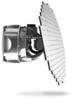
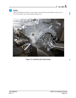
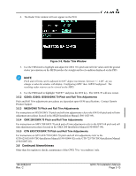
3.5 Post Installation Configuration & Checkout NOTE The GWX 70 does not provide valid outputs until the aircraft post installation configuration procedures are completed. NOTE Installations that are unable to electronically display the software part number of the GWX 70 should affix a label on the GWX 70 LRU marked with the software part number to meet the TSO marking requirements. For the installer's convenience, a label has been applied adjacent to the LRU serial number tag. When installed as part of a GX000 Garmin integrated flight deck, the GWX 70 must have FAA approved configuration data. Configuration data is loaded to the GWX 70 from an aircraft-specific GX000 Software Loader Card. Settings are predetermined for a specific aircraft and are typically contained with the file name "GWX". The PFD serves as the graphics user interface to the installer configuration the system. For sample configuration and checkout procedures, refer to the G1000 Line Maintenance Manual and Configuration Manual, Garmin part number 190-00303-04. Always use aircraft manufacturer approved checkout documents when performing actual checkouts. For GWX 70 installations operating with a Garmin MX20, refer to the GWX 68/MX20 unit configuration instructions in the MX20 Installation Manual, 560-1025-09. For GWX 70 installations operating with a Garmin GMX 200, refer to the GWX 68/GMX 200 unit configuration instructions in the GMX 200 Installation Manual, 190-00607-04. For GWX 70 installations operating with a Garmin GTN 6XX/7XX, refer to the GTN 625/635/650 TSO Installation Manual (190-01004-02) or the GTN 725/750 TSO Installation Manual (190-01007-02). 3.5.1 G1000/GWX 70 Pitch and Roll Trim Adjustments The following procedure assumes the correct configuration data files have been loaded and the system is in normal operating mode. The procedure is best performed during flight. 1. The aircraft should be airborne, flying in a straight and level attitude as indicated by the PFD attitude indicator. 2. View the Weather Radar page on the MFD and ensure that ground clutter is clearly visible and matches the ground/sky presentation on the PFD attitude indicator. 3. On the PFD press the following softkey sequence: 11, 11, 1, 1, 2. NOTE Step 3 must be preformed on PFD 1 in a 3-display system. GWX 70 Installation Manual Page 3-12 190-00829-01 Rev. C
-
 1
1 -
2
-
3
-
4
-
5
-
6
-
7
-
8
-
9
-
10
-
11
-
12
-
13
-
14
-
15
-
16
-
17
-
18
-
19
-
20
-
21
-
22
-
23
-
24
-
25
-
26
-
27
-
28
-
29
-
30
-
31
-
32
-
 33
33 -
 34
34 -
 35
35 -
 36
36 -
 37
37 -
 38
38 -
 39
39 -
 40
40 -
 41
41 -
 42
42 -
 43
43 -
44
-
45
-
46
-
47
-
48
-
49
-
50
-
51
-
52
-
53
-
54
-
55
-
56
-
57
-
58
-
59
-
60
-
61
-
62
-
63
-
64
-
65
 |
 |