Garmin Panoptix PS30 Installation Instructions - Page 2
Installing the Transducer on a Transom, Installing the Transducer on a Trolling Motor - down
 |
View all Garmin Panoptix PS30 manuals
Add to My Manuals
Save this manual to your list of manuals |
Page 2 highlights
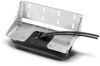
trolling motor (downward if mounted on the shaft, upward if mounted below the motor). • For a forward-facing transducer mounted on a transom mount, the cables should be routed out of the transducer toward the transom. Transducer Mounting Angle Considerations NOTICE The forward-view mount is not rated for speeds over 40 km/h (25 mph). • The internal attitude heading and reference system (AHRS) sensor detects the mounting angle of the transducer in relation to the water surface. When the Use AHRS setting is turned off in the chartplotter installation menu, it is assumed the transducer is mounted at a 45-degree angle and the down-view transducer is mounted at a 0-degree angle. • The higher the degree of the mounting angle and the more vertical the transducer, the less a strong bottom echo interferes with viewing targets in the water. To see more suspended targets, you should mount the transducer at a higher-degree, more vertical angle. • To reduce rings that can appear with a strong bottom echo, you should mount the transducer at a higher degree, more vertical angle. Installing the Transducer on a Transom Assembling the Transom-Mount Hardware 1 Attach the transducer mount bracket to the transducer À Á using four of the included 7 mm M4 mounting screws and  M4 lock washers . à 2 Attach the transducer mount bracket to the transom mount bracket using the included 16 mm M8 bolts , M8 flat Ä Å washers , and M8 lock nuts . Æ Ç 3 Route the Ethernet cable to the installation location of the network switch or to the back of the MFD. NOTE: The cable should not be routed close to electrical wires or other sources of electrical interference. TIP: Cutting the cables is not recommended, but a field installation kit can be purchased from Garmin or a Garmin dealer if cutting the cables is necessary. 4 Route the power cable to a 12 Vdc power source. Installing the Transom-Mount Hardware NOTICE If you are mounting the bracket on fiberglass with screws, it is recommended to use a countersink bit to drill a clearance counterbore through only the top gel-coat layer. This will help to avoid any cracking in the gel-coat layer when the screws are tightened. 1 Position the transducer mount so the bottom of the À transducer sits below the water line. 2 Mark the location of the holes of the transducer mount. 3 U15simngma(149/m32min(.5)/3d2eienp.) bit, drill the pilot holes approximately at the marked locations. 4 Apply marine sealant to four of the provided 8 mm M4 mounting screws, and attach the transducer assembly to the transom using the M4 screws and M4 lock washers. TIP: On boats with thinner hulls, you can place a wood backing block inside the hull at the mounting spot to lessen the pressure on the mounting screws. 5 If possible, route the cables to come out of the transducer on the starboard side. NOTE: If you must route the cables to come out the port side, you must select the Flipped option in your chartplotter installation menu for an accurate display. 6 For the downward-facing transducer, adjust the mount so the transducer points straight down. 7 For the forward-facing transducer, adjust the mount so the transducer points toward the front of the boat at an angle based on the transducer mounting angle considerations. 8 For the forward-facing transducer, adjust the bolt tension to allow the mount to close if the transducer collides with an object. Installing the Transducer on a Trolling Motor Trolling Motor Mount Considerations • Placement of the transducer on a trolling motor depends on the type of trolling motor you have installed on your boat. Check with your trolling motor manufacturer for information on the proper placement of your trolling motor mount. • The transducer should be mounted on the shaft on most cable-steered trolling motors, because the motor may not be rugged enough to support the weight of the transducer and mount. This mounting location blocks the view directly below the trolling motor, but allows for a longer-range forward view because there is less bottom interference. Mounting the transducer on the shaft also offers more protection, and the weight of the transducer and mounting hardware place less strain on the trolling motor system • The transducer should not be mounted on the motor of some types of trolling motors, because the transducer can damage the steering cables and bearings, and it can hit the boat hull during deployment and retraction. • The transducer can be mounted on the motor of some handsteered and wireless trolling motors, but you must make sure you can safely deploy and retract the trolling motor with the transducer attached. • On trolling motors with steering cables, place the transducer as close to the center line of rotation as possible to decrease the resistance on the motor. 2
-
 1
1 -
 2
2 -
 3
3 -
 4
4
 |
 |
