Garmin Panoptix PS30 Installation Instructions - Page 3
Specifications - installation
 |
View all Garmin Panoptix PS30 manuals
Add to My Manuals
Save this manual to your list of manuals |
Page 3 highlights
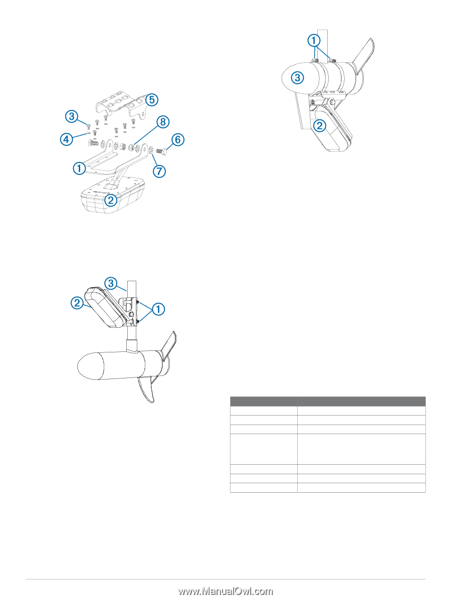
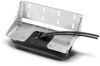
• Mount the transducer so it does not obstruct the motor from its storage cradle or prevent the motor from being stowed and deployed correctly. Assembling the Trolling-Mount Hardware 1 Attach the transducer mount bracket to the transducer À Á using the included 7 mm M4 mounting screws and M4 lock  washers . à 2 Attach the transducer mount bracket to the trolling mount bracket using the included 16 mm M8 bolts , M8 flat Ä Å washers , and M8 lock nuts . Æ Ç Attaching the Transducer to a Trolling Motor Shaft 1 Insert the hose clamps through the slots on the trolling À motor mount . Á 2 Slide the hose clamps around the trolling motor shaft .  3 Tighten the hose clamps. 4 Secure the transducer cable to the shaft or other secure location. 5 Route the Ethernet cable to the installation location of the network switch or to the back of the chartplotter. NOTE: The cable should not be routed close to electrical wires or other sources of electrical interference. 6 Route the power cable to a 12 Vdc power source. 7 Adjust the mount so it points toward the front of the boat at an angle based on the transducer angle considerations. Attaching the Transducer to a Trolling Motor 1 Insert the hose clamps through the slots on the trolling À motor mount . Á 2 Slide the hose clamps around the trolling motor .  3 With the motor placed as close to the center line of rotation as possible, tighten the hose clamps. 4 Secure the transducer cable to the motor shaft or other secure location. NOTE: Ensure the trolling motor and transducer clear the boat during deployment and retraction. 5 Route the Ethernet cable to the installation location of the network switch or to the back of the MFD while taking these precautions: • The cable should not be routed close to electrical wires or other sources of electrical interference. • The cable must not be pinched when the trolling motor is deployed and retracted. • Cutting the cables is not recommended, but a field installation kit can be purchased from Garmin or a Garmin dealer if cutting the cables is necessary. 6 Add cable wraps to secure the cable, and provide a circular service loop to allow the trolling motor to rotate. 7 Route the power cable to a 12 Vdc power source. 8 For a downward-facing transducer, adjust the mount so the transducer points straight down. 9 For a forward-facing transducer, adjust the mount so the transducer points toward the front of the boat at an angle based on the transducer mounting angle considerations. Specifications Specification Measurement Dimensions (W x H x L) 9.1 x 4.2 x 17 cm (3.6 x 1.7 x 6.7 in.) Weight 800 g (1.8 lb.) Max. power usage 10 W Temperature range • Operating: From 0 to 40°C (from 32 to 104°F) • Storage: From -40 to 70°C (from -40 to 158°F). Material ASA plastic Maximum depth* 91 m (300 ft.) Frequency 417 kHz * Dependent upon transducer placement, water salinity, bottom type, and other water conditions. 3
-
 1
1 -
 2
2 -
 3
3 -
 4
4
 |
 |