Garmin Reactor 40 Kicker Autopilot Reactor 40 Kicker Suzuki Adapter Installati - Page 3
Assembling the Carburetor Linkage, Connecting the Throttle Actuator Cable to the, Carburetor Linkage
 |
View all Garmin Reactor 40 Kicker Autopilot manuals
Add to My Manuals
Save this manual to your list of manuals |
Page 3 highlights
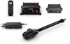
3 Connect the throttle actuator cable to the carburetor linkage (Connecting the Throttle Actuator Cable to the Carburetor Linkage, page 3). 4 Assemble the parts in this adapter kit and secure them to the motor (Throttle Actuator Component Connections, page 3). 5 Using the Reactor 40 Kicker Throttle Actuator Installation Instructions , complete and test the throttle actuator installation. Assembling the Carburetor Linkage The carburetor linkage allows the throttle cable from the actuator to pull open the carburetor throttle lever on the motor. 1 Using the parts provided in this adapter kit, place the carburetor linkage bracket on the tapered end of the carburetor linkage arm . Part Throttle actuator cable (from the throttle actuator box) Notes You should connect the throttle actuator cable to the carburetor linkage before securing it to the throttle cable bracket (Connecting the Throttle Actuator Cable to the Carburetor Linkage, page 3). Throttle cable bracket Manifold mounting location Carburetor linkage1 You must secure the throttle actuator cable to the throttle cable bracket using the included screws (Securing the Throttle Actuator Cable to the Bracket, page 3). You must remove the existing bolt on the manifold and use it to secure the throttle cable bracket . You must assemble the carburetor linkage before installing it (Assembling the Carburetor Linkage, page 3). The carburetor linkage arm is keyed to fit only one way on the carburetor. 2 Using the bolt and nut provided in this adapter kit, fasten the bracket to the arm. 3 Tighten the nut so the bracket is securely connected to the arm, but loose enough so the bracket moves freely. Connecting the Throttle Actuator Cable to the Carburetor Linkage The carburetor linkage is designed to hold the cable from the throttle actuator securely. Because of the design, you must connect the throttle actuator cable to the carburetor linkage before you secure the parts to the motor. 1 If necessary, assemble the carburetor linkage (Assembling the Carburetor Linkage, page 3). 2 Place the round end of the throttle actuator cable into the hole on the end of the carburetor linkage. Securing the Throttle Actuator Cable to the Bracket Before securing the cable to the bracket, you should connect the end of the throttle actuator cable to the carburetor linkage (Connecting the Throttle Actuator Cable to the Carburetor Linkage, page 3). 1 Place the top of the bracket over the raised portion of the throttle actuator cable . 3 Rotate the cable so it feeds through the slot on the end of the linkage. Throttle Actuator Component Connections 2 Secure the cable to the bracket using the included screws . Setting the Linkage Components for Proper Idle After you install the throttle actuator components on the motor, you must adjust them so the motor idles correctly. 1 Loosen the throttle actuator bracket on the engine manifold until the throttle actuator does not pull open the carburetor throttle lever. There should be obvious slack in the throttle actuator cable. 2 Adjust the tiller throttle to idle, start the motor, and complete an action: • If the motor is not idling correctly, loosen the set screw on the carburetor throttle lever, adjust the tiller throttle linkage rod until the motor idles correctly, and tighten the set screw. • If the motor idles correctly, proceed to the next step. 3 Using the tiller throttle, increase the speed of the motor, and complete an action: • If the motor does not increase its speed and return to idle correctly, repeat the previous step to adjust the tiller throttle linkage rod. Installation Instructions 1 There is a black rubber pad on the motor manifold that may interfere with the movement of the carburetor linkage. If the throttle actuator cannot increase the throttle beyond idle because it contacts the rubber pad, you can trim or smooth the pad to prevent contact. 3
-
 1
1 -
 2
2 -
 3
3 -
 4
4 -
 5
5 -
 6
6 -
 7
7 -
 8
8 -
 9
9 -
10
-
11
-
12
-
13
-
14
-
15
-
16
-
17
-
18
-
19
-
20
-
21
-
22
-
23
-
24
-
25
-
26
-
27
-
28
-
29
-
30
-
31
-
32
-
33
-
34
-
35
-
36
-
37
-
38
-
39
-
40
 |
 |
