Gateway NV-59C Service Guide - Page 53
Disassembly Process, IMPORTANT, Main Screw List, Screw, Quantity, Part Number
 |
View all Gateway NV-59C manuals
Add to My Manuals
Save this manual to your list of manuals |
Page 53 highlights
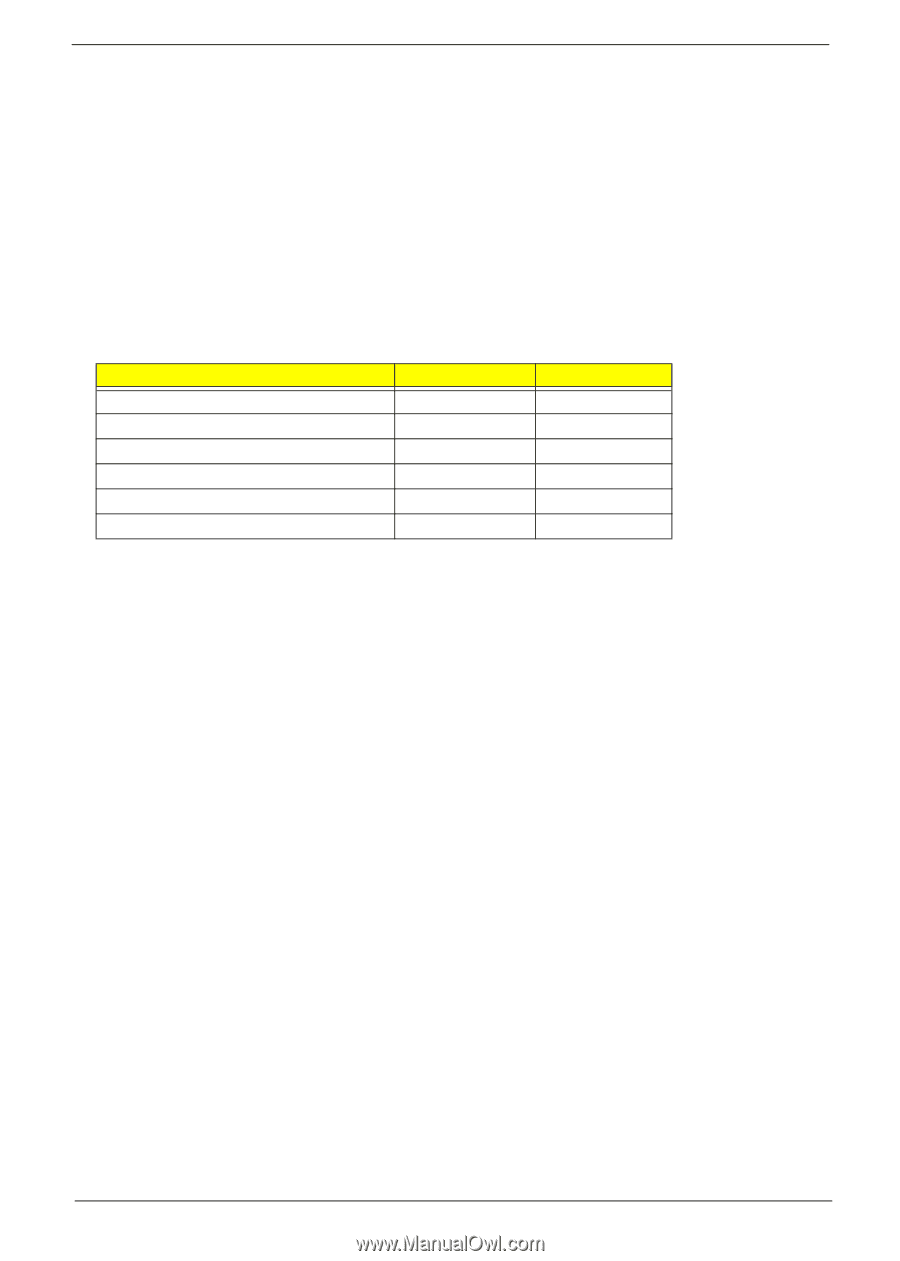
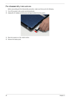
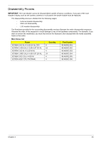
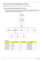
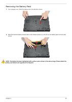
Disassembly Process IMPORTANT: The LCD Module cannot be disassembled outside of factory conditions. If any part of the LCD Module is faulty, such as the camera, antenna or LCD panel, the whole module must be replaced. The disassembly process is divided into the following stages: • External module disassembly • Main unit disassembly • LCD module disassembly The flowcharts provided in the succeeding disassembly sections illustrate the entire disassembly sequence. Observe the order of the sequence to avoid damage to any of the hardware components. For example, if you want to remove the mainboard, you must first remove the keyboard, then disassemble the inside assembly frame in that order. Main Screw List Screw SCREW 2.5D 5L K 5.5D ZK NL CR3 SCREW 2.45D 8.0L K 5.5D 0.8T ZK NL SCREW 2.5D 6L K 5.5D NI NL SCREW 1.98D 3.0L K 4.6D 0.8T ZK NL SCREW 3.0D 3.0L K 4.9D NI SCREW ASSY CPU THERMAL Quantity 9 19 4 24 4 4 Part Number 86.WJ802.001 86.WJ802.002 86.WJ802.003 86.WJ802.004 86.WJ802.005 86.WJ802.006 Chapter 3 43
-
 1
1 -
2
-
3
-
4
-
5
-
6
-
7
-
8
-
9
-
10
-
11
-
12
-
13
-
14
-
15
-
16
-
17
-
18
-
19
-
20
-
21
-
22
-
23
-
24
-
25
-
26
-
27
-
28
-
29
-
30
-
31
-
32
-
33
-
34
-
35
-
36
-
37
-
38
-
39
-
40
-
41
-
42
-
43
-
44
-
45
-
46
-
47
-
 48
48 -
 49
49 -
 50
50 -
 51
51 -
 52
52 -
 53
53 -
 54
54 -
 55
55 -
 56
56 -
 57
57 -
 58
58 -
59
-
60
-
61
-
62
-
63
-
64
-
65
-
66
-
67
-
68
-
69
-
70
-
71
-
72
-
73
-
74
-
75
-
76
-
77
-
78
-
79
-
80
-
81
-
82
-
83
-
84
-
85
-
86
-
87
-
88
-
89
-
90
-
91
-
92
-
93
-
94
-
95
-
96
-
97
-
98
-
99
-
100
-
101
-
102
-
103
-
104
-
105
-
106
-
107
-
108
-
109
-
110
-
111
-
112
-
113
-
114
-
115
-
116
-
117
-
118
-
119
-
120
-
121
-
122
-
123
-
124
-
125
-
126
-
127
-
128
-
129
-
130
-
131
-
132
-
133
-
134
-
135
-
136
-
137
-
138
-
139
-
140
-
141
-
142
-
143
-
144
-
145
-
146
-
147
-
148
-
149
-
150
-
151
-
152
-
153
-
154
-
155
-
156
-
157
-
158
-
159
-
160
-
161
-
162
-
163
-
164
-
165
-
166
-
167
-
168
-
169
-
170
-
171
-
172
-
173
-
174
-
175
-
176
-
177
-
178
-
179
-
180
-
181
-
182
-
183
-
184
-
185
-
186
-
187
-
188
-
189
-
190
-
191
-
192
-
193
-
194
-
195
-
196
-
197
-
198
-
199
-
200
-
201
-
202
-
203
-
204
-
205
-
206
-
207
-
208
-
209
-
210
-
211
-
212
-
213
-
214
-
215
-
216
-
217
-
218
-
219
-
220
-
221
-
222
 |
 |