GE 60-880-95 Installation Instructions - Page 2
Mounting the Sensor
 |
UPC - 046188089604
View all GE 60-880-95 manuals
Add to My Manuals
Save this manual to your list of manuals |
Page 2 highlights
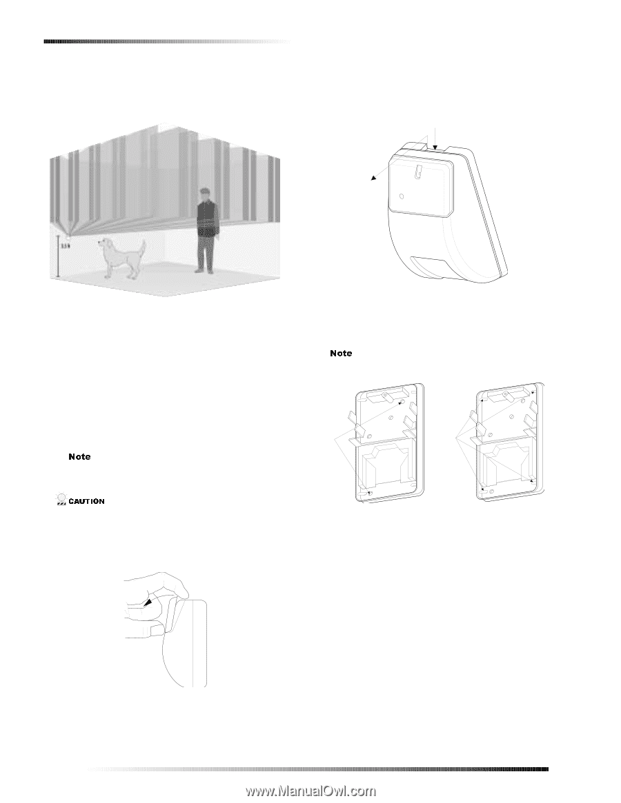
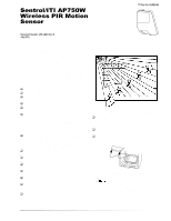
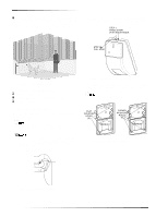
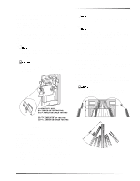
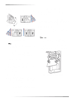
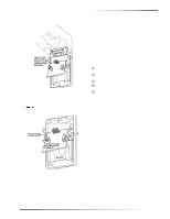
Mounting the Sensor ‰ For installations where pets are present, mount the sensor upside down about 3.5 feet above the floor (see Figure 3). Leave the factory-installed undercrawl mask in place to block any detection pattern directed at the ceiling. 2. Open the sensor housing by pressing down on the top rear and pulling the front cover at the top (see Figure 5). Set the front cover aside. S TE P 1: PRESS DO W N W IT H IN D E X . IN G E R S TE P 2: P U LL A W A Y Figure 3. Pet Alley Application Tools and Supplies Needed ‰ Phillips screwdriver ‰ Anchors and screws for mounting (included) ‰ Masks (included) Mounting the Sensor This section describes how to mount the sensor on a flat wall or in a corner. 1RWH Remove the factory-installed plastic masks before mounting. Re-install as desired after walk testing. &$87,21 You must be free of all static electricity before handling sensor circuit boards. Touch a grounded, bare metal surface before touching circuit boards or wear a grounding strap. 1. Remove the small cover (see Figure 4). Figure 5. Opening the Sensor Housing 3. Mount the sensor on a flat wall or in a corner, using the appropriate mounting holes (see Figure 6). Use wall anchors and screws to secure the sensor. 1RWH Avoid touching the mirror. Fingerprints may affect detection coverage. .LA T M O U N T IN G H O LE S (2 ) M IR R O R CO RNER M O U N T IN G H O LE S (4 ) M IR R O R Figure 6. Mounting Hole Locations Figure 4. Removing the Small Cover 2
-
 1
1 -
 2
2 -
 3
3 -
 4
4 -
 5
5 -
 6
6
 |
 |