GE 60-880-95 Installation Instructions - Page 3
Setting the Sensor Coverage Area, and Sensitivity, Walk Testing, Installing Masks
 |
UPC - 046188089604
View all GE 60-880-95 manuals
Add to My Manuals
Save this manual to your list of manuals |
Page 3 highlights
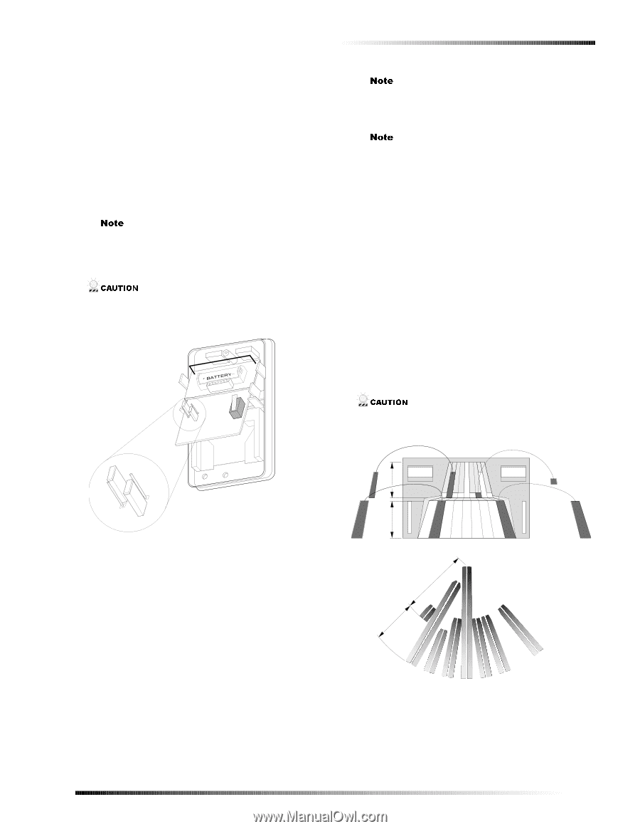
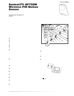
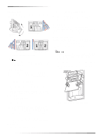
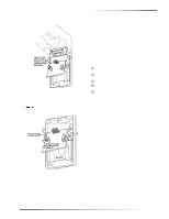
Setting the Sensor Coverage Area and Sensitivity Setting the Sensor Coverage Area and Sensitivity Jumper J1 determines the sensitivity mode of the sensor, either standard or bi-curtain. Jumper J2 determines the coverage area of the sensor, either 33 or 50 feet. See Figure 7 for jumper positions. Use the standard (STD) setting for wide-angle coverage and single curtain pattern. Use the bi-curtain (BI) setting for added stability to help reduce false alarms. This mode requires intruders to be detected by two curtains of coverage. 1RWH Do not use the bi-curtain mode for detection in areas within 5 feet of the sensor. When selecting bi-curtain mode, always leave the cardboard undercrawl mask installed. &$87,21 You must be free of all static electricity before handling sensor circuit boards. Touch a grounded, bare metal surface before touching circuit boards or wear a grounding strap. J1 J2 1RWH Excessive use of the walk test mode may reduce battery life. Use only for initial setup and maintenance testing. 1RWH In normal operation mode, the sensor only transmits an alarm signal 135 seconds after the previous alarm. This reduces unnecessary RF transmissions in high traffic areas, thereby extending battery life. Environment Testing Activate the walk test mode, then turn on all heating or air conditioning sources which would normally be active during the protection period. Stand away from the sensor and outside the coverage pattern and watch for alarms. Installing Masks After determining the full coverage area and performing the environment test, you may need or want to mask (block) certain parts of the coverage. Self-Adhesive Masks Block the appropriate mirror sections with these masks. Figure 8 shows an example of where to apply the masks and the resulting coverage area. &$87,21 To avoid damaging the mirror, do not remove masks using a sharp tool. If necessary, remove masks by carefully peeling them off with your fingers. J1 J2 J 1 -S E N S IT IV IT Y M O D E B I = J U M P E R O N T O P T W O P IN S S T D = J U M P E R O N L O W E R T W O P IN S J 2 -C O V E R A G E A R E A 5 0 . T = J U M P E R O N T O P T W O P IN S 3 3 . T = J U M P E R O N L O W E R T W O P IN S Figure 7. Sensitivity Mode and Coverage Area Jumper Settings Walk Testing Walk testing should be done to determine the actual coverage area of the sensor. The edge of the coverage pattern is determined by the first LED flash. This may change slightly depending on the sensitivity setting. Walk test the unit from both directions to determine the pattern boundaries. 1. Remove the sensor cover to activate the tamper switch, then reattach it to activate the 2-minute walk test mode. 2. Walk across the coverage pattern to determine the coverage area, indicated by LED activation. After 2 minutes, the walk test mode and the LED will no longer activate when motion is detected. A 123 4 567 89 1 2 3456 789 B A B 9 1 8 2 7 3 6 5 4 Figure 8. Installing Self-Adhesive Masks 3
-
 1
1 -
 2
2 -
 3
3 -
 4
4 -
 5
5 -
 6
6
 |
 |