GE AZ41E12DAC Owners Manual - Page 13
Installation Instructions, HOW TO CONNECT, ELECTRICAL SUBBASE, CONNECTION, 208 VOLT ELECTRICAL
 |
View all GE AZ41E12DAC manuals
Add to My Manuals
Save this manual to your list of manuals |
Page 13 highlights
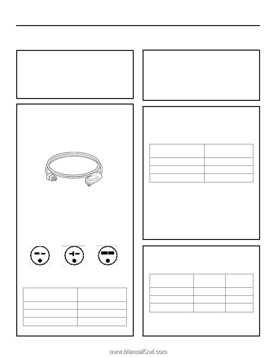
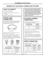
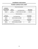
Installation Instructions 230/208 VOLT ELECTRICAL CONNECTION OPTIONS HOW TO CONNECT 1. Remove the room cabinet. 2. Connect to electrical power. 3. Review the following steps for applicable supply voltages. 4. Reinstall the room cabinet. Power cords may include an arc fault interruption or a leakage current detection interruption device. A test and reset button is provided on the plug case or the inline case. The device should be tested on a periodic basis by first pressing the TEST button and then the RESET button. If the TEST button does not trip or if the RESET button will not stay engaged, discontinue use of the Zoneline and contact a qualified service technician. POWER CORD CONNECTION A power supply kit with LCDI must be used to supply power to the Zoneline unit. The appropriate kit is determined by the voltage, the means of electrical connection and the amperage of the branch circuit. appearance may vary. Power supply kit Connections of 208 or 230-volt circuits may be with a power supply kit or a junction box kit. All wiring, including installation of the receptacle, must be in accordance with the NEC and local codes, ordinances and regulations. Codes require the use of an arc fault or leakage current detection device on the power cord except direct connect. Be sure to select the correct cord for your installation. ELECTRICAL SuBBASE CONNECTION 230/208-volt models may be installed using one of the following electrical subbases: Branch Circuit and Unit Amperage Rating Proper GE Subbase Kit 15 RAK204D15P 20 RAK204D20P 30 RAK204D30P* *Not approved for use on 7000 BTU models. Electrical subbases provide an enclosure for direct connection or enclosed receptacles. The subbase kit includes the power cord. The instructions provided with the selected subbase kit must be carefully followed. It is the responsibility of the installer to ensure the connection of components is done in accordance with these instructions and all electrical codes. Tandem 15 Amp. Perpendicular 20 Amp. Large Tandem 30 Amp. 230/208-volt receptacle configuration. Branch Circuit and Unit Amperage Rating 15 20 30 Proper GE Power Cord with LCDI Device RAK3153A RAK3203A RAK3303* *Not approved for use on 7000 BTU models. DIRECT CONNECTION Order the following Kit for 230/208-volt direct connection as required: Branch Circuit and Unit Amperage Rating 15 20 30 Power Supply Accessory RAK4002A RAK4002A RAK4002A Power Supply Kit RAK4157 RAK4207 RAK4307* *Not approved for use on 7000 BTU models. Skip to the "MAKE ELECTRICAL CONNECTION TO THE UNIT" section. 13
-
 1
1 -
2
-
3
-
4
-
5
-
6
-
7
-
 8
8 -
 9
9 -
 10
10 -
 11
11 -
 12
12 -
 13
13 -
 14
14 -
 15
15 -
 16
16 -
 17
17 -
 18
18 -
19
-
20
-
21
-
22
-
23
-
24
-
25
-
26
-
27
-
28
-
29
-
30
-
31
-
32
-
33
-
34
-
35
-
36
-
37
-
38
-
39
-
40
-
41
-
42
-
43
-
44
-
45
-
46
-
47
-
48
-
49
-
50
-
51
-
52
-
53
-
54
-
55
-
56
-
57
-
58
-
59
-
60
-
61
-
62
-
63
-
64
-
65
-
66
-
67
-
68
-
69
-
70
-
71
-
72
 |
 |