GE DPVH880GJMV Owners Manual - Page 23
Installation Instructions, EXHAUSTING THE DRYER, WARNING
 |
UPC - 084691169796
View all GE DPVH880GJMV manuals
Add to My Manuals
Save this manual to your list of manuals |
Page 23 highlights
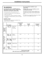
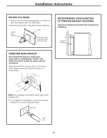
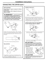
Installation Instructions EXHAUSTING THE DRYER WARNING - To reduce the risk of fire or personal injury: • This clothes dryer must be exhausted to the outdoors. • Use only 4″ rigid metal ducting for the home exhaust duct. • Use only 4″ rigid metal or UL-listed flexible metal (semi-rigid or foil-type) duct to connect the dryer to the home exhaust duct. It must be installed in accordance with the instructions found in "Connecting the Dryer to House Vent" on page 24 of this manual. • Do not terminate exhaust in a chimney, a wall, a ceiling, gas vent, crawl space, attic, under an enclosed floor, or in any other concealed space of a building. • Never terminate the exhaust into a common duct with a kitchen exhaust system. A combination of grease and lint creates a potential fire hazard. • Do not use duct longer than specified in the exhaust length table. Longer ducts can accumulate lint, creating a potential fire hazard. • Never install a screen in or over the exhaust duct. This will cause lint to accumulate, creating a potential fire hazard. • Do not assemble ductwork with any fasteners that extend into the duct. These fasteners can accumulate lint, creating a potential fire hazard. • Do not obstruct incoming or exhausted air. • Provide an access for inspection and cleaning of the exhaust system, especially at turns and joints. Exhaust system shall be inspected and cleaned at least once a year. • This dryer comes ready for rear exhausting. If space is limited, use the instructions on pages 28-31 to exhaust directly from the sides or bottom of the cabinet . TOOLS AND MATERIALS YOU WILL NEED TO INSTALL EXHAUST DUCT EXHAUST SYSTEM CHECKLIST HOOD OR WALL CAP • Terminate in a manner to prevent back drafts or entry of birds or other wildlife. • Termination should present minimal resistance to the exhaust airflow and should require little or no maintenance to prevent clogging. • Never install a screen in or over the exhaust duct. • Wall caps must be installed at least 12″ above ground level or any other obstruction with the opening pointed down. SEPARATION OF TURNS • For best performance, separate all turns by at least 4 ft. of straight duct, including distance between last turn and dampened wall cap. For turns less than 4 ft. apart, see the Ducting Component Equivalency Chart. SEALING OF JOINTS • All joints should be tight to avoid leaks. The male end of each section of duct must point away from the dryer. • Do not assemble the ductwork with fasteners that extend into the duct. They will serve as a collection point for lint. • Duct joints should be made air- and moisture-tight by wrapping the overlapped joints with duct tape or aluminum tape. • Horizontal runs should slope down towards outdoors 1/4″ per foot. INSULATION • Ductwork that runs through an unheated area or is near air conditioning should be insulated to reduce condensation and lint buildup. Ì Phillips-head screwdriver Ì Drill with 1/8″ drill bit (for bottom venting) Ì Duct tape or duct clamp Ì Hacksaw Ì Rigid or UL-listed flexible metal 4″ (10.2 cm) duct Ì Vent hood 23
-
 1
1 -
2
-
3
-
4
-
5
-
6
-
7
-
8
-
9
-
10
-
11
-
12
-
13
-
14
-
15
-
16
-
17
-
 18
18 -
 19
19 -
 20
20 -
 21
21 -
 22
22 -
 23
23 -
 24
24 -
 25
25 -
 26
26 -
 27
27 -
 28
28 -
29
-
30
-
31
-
32
-
33
-
34
-
35
-
36
-
37
-
38
-
39
-
40
-
41
-
42
-
43
-
44
-
45
-
46
-
47
-
48
-
49
-
50
-
51
-
52
-
53
-
54
-
55
-
56
-
57
-
58
-
59
-
60
-
61
-
62
-
63
-
64
-
65
-
66
-
67
-
68
-
69
-
70
-
71
-
72
-
73
-
74
-
75
-
76
-
77
-
78
-
79
-
80
-
81
-
82
-
83
-
84
-
85
-
86
-
87
-
88
-
89
-
90
-
91
-
92
-
93
-
94
-
95
-
96
-
97
-
98
-
99
-
100
-
101
-
102
-
103
-
104
-
105
-
106
-
107
-
108
-
109
-
110
-
111
-
112
-
113
-
114
-
115
-
116
-
117
-
118
-
119
-
120
-
121
-
122
-
123
-
124
-
125
-
126
-
127
-
128
-
129
-
130
-
131
-
132
-
133
-
134
-
135
-
136
-
137
-
138
-
139
-
140
-
141
-
142
-
143
-
144
-
145
-
146
-
147
-
148
-
149
-
150
-
151
-
152
 |
 |
