GE GDF540HSDSS Installation Instructions - Page 10
Step 14: Position Dishwasher, Secure, To Countertop Or Cabinet, Step 15, Connect Water Supply, Step
 |
View all GE GDF540HSDSS manuals
Add to My Manuals
Save this manual to your list of manuals |
Page 10 highlights
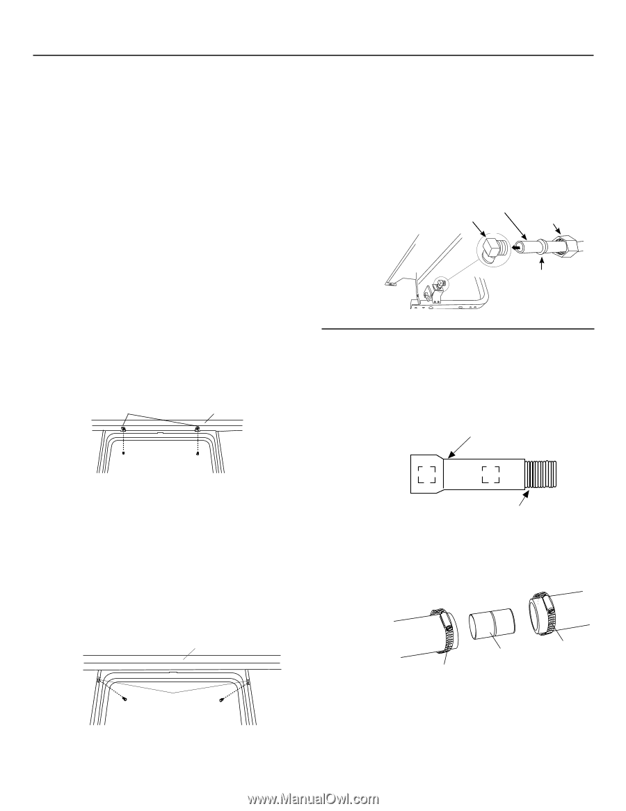
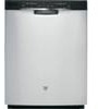
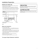
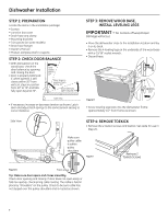
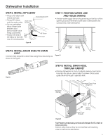
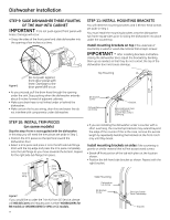
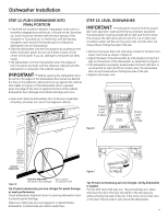
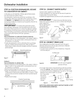
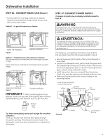
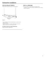
Dishwasher Installation STEP 14: POSITION DISHWASHER, SECURE TO COUNTERTOP OR CABINET In this step you will need the 2 Phillips special head screws from the screws set aside in Step 1. The dishwasher must be secured to the countertop or the cabinet sides. When the underside of the countertop is wood, use Method 1. Use Method 2 when the underside of the countertop is made of a material, such as granite, that will not accept wood screws. IMPORTANT - Prevent door panel and control panel damage. Dishwasher must be positioned so the front panel and control panel do not contact the adjacent cabinets or countertop. Mounting screws must be driven straight and flush. Protruding screw heads could scratch the door panel or control panel and interfere with door operation. Method 1 Secure dishwasher to underside of wood countertop. • Recheck alignment of the dishwasher in the cabinet. Refer to Steps 12 and 13. Door panel and/or control panel must not hit cabinets or countertop. • Fasten the dishwasher to the underside of the countertop with the 2 Phillips special head screws. Refer to Figure T. Make certain screws are driven straight and flush to prevent panel damage. Brackets Wood Countertop STEP 15: CONNECT WATER SUPPLY Connect water supply line to 90° elbow. • Slide compression nut, then ferrule over end of water line. • Insert water line into 90° elbow. • Slide ferrule against elbow and secure with compression nut. IMPORTANT - Check to be sure that door spring and/or door spring cable do not rub or contact the fill hose or water supply line. Test by opening and closing the door. Reroute the water Hot Water Supply Line 90° Elbow Compression Nut supply lines if a rubbing noise or interference occurs. Ferrule Figure V Bottom Left Side STEP 16: CONNECT DRAIN LINE The molded end of the drain hose will fit 5/8" through 1" diameter inlet ports on the air gap, waste tee or disposer. • Determine size of inlet port. • Cut drain hose connector on the marked line, if required, to fit the inlet port. Cutting Line Figure T 1" 5/8" Method 2 Secure dishwasher to cabinet sides. 923-10KK • Recheck alignment of the dishwasher in the cabinet. Refer to Steps 12 and 13. Door panel and/or control panel must not hit cabinets or countertop. • Remove button plugs from side of tub well. • Fasten the dishwasher to the adjacent cabinets with the 2 Phillips special head screws provided. Refer to Figure U. Make certain screws are driven straight and flush to prevent panel damage. • Replace button plugs. Granite Countertop Figure U Side Brackets Figure W IMPORTANT: Do not cut corrugated portion of hose • If a longer drain hose is required and you did not purchase drain hose GPF12L, add up to 66" length for a total of 144" 1871 Art4 (12 feet) to the factory-installed hose. Use 5/8" or 7/8" inside diameter hose and a coupler to connect the 2 hose ends. Secure the connection with hose clamps. Hose Clamp Coupler Figure X Hose Clamp Note: TOTAL DRAIN HOSE LENGTH MUST NOT EXCEED 12 FEET FOR PROPER DRAIN OPERATION0.5A-1183DD 05A-1182Q 10
-
 1
1 -
2
-
3
-
4
-
 5
5 -
 6
6 -
 7
7 -
 8
8 -
 9
9 -
 10
10 -
 11
11 -
 12
12 -
 13
13 -
 14
14 -
 15
15 -
16
-
17
-
18
-
19
-
20
-
21
-
22
-
23
-
24
-
25
-
26
-
27
-
28
-
29
-
30
-
31
-
32
 |
 |