GE JVM3670WF Installation Instructions
GE JVM3670WF - Profile Spacemaker XL 1800 36" Microwave Oven Manual
 |
UPC - 084691078319
View all GE JVM3670WF manuals
Add to My Manuals
Save this manual to your list of manuals |
GE JVM3670WF manual content summary:
- GE JVM3670WF | Installation Instructions - Page 1
Installation Instructions Over the Range Microwave Oven JVM3660, JVM3670 Questions? Call 800.GE.CARES (800.432.2737) or Visit our Website at: GEAppliances.com BEFORE YOU BEGIN Read these instructions completely and carefully. • IMPORTANT - Save these instructions for local inspector's use. • - GE JVM3670WF | Installation Instructions - Page 2
General information Important Safety Instructions 3 Electrical Requirements 3 Hood Exhaust 4, 5 Damage - Shipment/Installation 6 Parts Included 6 Tools You Will Need 7 Mounting Space 7 C Recirculating 19-22 Attach Mounting Plate to Wall 19 Preparation of Top Cabinet 19 Check Microwave - GE JVM3670WF | Installation Instructions - Page 3
beginning installation to avoid severe or fatal shock injury. CAUTION: For personal safety, the mounting surface must be capable of supporting the above the microwave oven. The outlet box and supply circuit should be installed by a qualified electrician and conform to the National Electrical Code or - GE JVM3670WF | Installation Instructions - Page 4
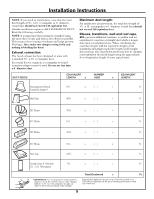
Installation Instructions HOOD EXHAUST NOTE: Read these next two pages page 6. OUTSIDE TOP EXHAUST (EXAMPLE ONLY) The following chart describes an example of one possible ductwork installation. DUCT PIECES EQUIVALENT NUMBER EQUIVALENT LENGTH x USED = LENGTH Roof Cap 24 Ft. x (1) = - GE JVM3670WF | Installation Instructions - Page 5
Installation Instructions NOTE: If you need to install ducts, note that the total duct length of 31⁄4″ x 10″ HOOD EXHAUST DUCT. Read the following carefully. NOTE: It is important that venting be installed using the most direct route and with as few elbows as possible. This ensures clear - GE JVM3670WF | Installation Instructions - Page 6
2 Tape You will find the installation hardware contained in a packet with the unit. Check to make sure you have all these parts. NOTE: Some extra parts are included. ADDITIONAL PARTS PART Top Cabinet Template QUANTITY 1 Installation 1 Instructions Separately 2 Packed Grease Filters 6 - GE JVM3670WF | Installation Instructions - Page 7
• This microwave oven is for installation over ranges up to 36″ wide. • If you are going to vent your microwave oven to the outside, see Hood Exhaust Section for exhaust duct preparation. • When installing the microwave oven beneath smooth, flat cabinets, be careful to follow the instructions on the - GE JVM3670WF | Installation Instructions - Page 8
1 PLACEMENT OF THE MOUNTING PLATE A. REMOVING THE MICROWAVE OVEN FROM THE CARTON/ REMOVING THE MOUNTING PLATE 1 Remove the installation instructions, filters, glass tray, and the small hardware bag. Do not remove the Styrofoam protecting the front of the oven. 2 Fold back all 4 carton flaps fully - GE JVM3670WF | Installation Instructions - Page 9
Installation Instructions C. DETERMINING WALL PLATE LOCATION UNDER YOUR CABINET Plate position - beneath flat bottom cabinet Plate position - beneath framed recessed cabinet bottom Mounting Plate Tabs Touching the Cabinet Bottom Mounting Plate Tabs Touching the Back Frame At least 36″ 30″ to - GE JVM3670WF | Installation Instructions - Page 10
Installation Instructions D. ALIGNING THE WALL PLATE Hole A Draw a Vertical Line on Wall from Center of Top Cabinet Hole B Hole C CAUTION: Wear gloves to avoid cutting fingers on sharp edges. Area E 1 Draw a vertical line on the wall at the center of the 36 support the weight of the microwave. - GE JVM3670WF | Installation Instructions - Page 11
Instructions 2 INSTALLATION TYPES (Choose A, B or C) This microwave oven is designed for adaptation to the following three types of ventilation: A. Outside Top Exhaust (Vertical Duct) B. Outside Back Exhaust (Horizontal Duct) C. Recirculating (Non-Vented Ductless) NOTE: This microwave - GE JVM3670WF | Installation Instructions - Page 12
Installation Instructions A OUTSIDE TOP EXHAUST (Vertical Duct) INSTALLATION OVERVIEW A1. Attach Mounting Plate to Wall A2. Prepare Top Cabinet A3. Check Damper Operation A4. Mount Microwave Oven A5. Adjust Exhaust Adaptor A6. Connect Ductwork A1. ATTACH THE MOUNTING PLATE TO THE WALL To use - GE JVM3670WF | Installation Instructions - Page 13
instructions on the TOP CABINET TEMPLATE. CAUTION: Wear safety goggles when drilling holes in the cabinet bottom. A3. CHECK FOR PROPER DAMPER OPERATION Blower Plate Exhaust Adaptor (absent on models shipped for recirculation exhaust) Damper A4. MOUNT THE MICROWAVE OVEN FOR EASIER INSTALLATION - GE JVM3670WF | Installation Instructions - Page 14
7 Tighten the remaining three screws to the top of the microwave oven. (While tightening screws, hold the microwave oven in place against the wall and the top cabinet.) 8 Install grease filters. See the Owner's Manual packed with the microwave. 1 Extend the house duct down to connect to the exhaust - GE JVM3670WF | Installation Instructions - Page 15
Installation Instructions B OUTSIDE BACK EXHAUST (Horizontal Duct) INSTALLATION OVERVIEW B1. Prepare Rear Wall B2. Attach Mounting Plate to Wall B3. Prepare Top Cabinet B4. Adjust Blower B5. Mount the Microwave Oven B1. PREPARING THE REAR WALL FOR OUTSIDE BACK EXHAUST F G H I This microwave oven - GE JVM3670WF | Installation Instructions - Page 16
Installation Instructions plate around both of the exhaust openings where it will touch the microwave. B2. ATTACH THE MOUNTING PLATE TO THE WALL Wall Bolt End FOR PREPARATION OF TOP CABINET You need to drill holes for the top support screws and a hole large enough for the power cord to fit - GE JVM3670WF | Installation Instructions - Page 17
Installation Instructions B4. ADAPTING MICROWAVE BLOWER FOR OUTSIDE BACK EXHAUST 1 Remove and save screw that holds blower motor to microwave. Blower Motor Back of Microwave of microwave oven. 7 Secure the blower unit to the microwave with the screw from Step 1. Blower Plate Back of Microwave Blower - GE JVM3670WF | Installation Instructions - Page 18
Installation Instructions B5. MOUNT THE MICROWAVE OVEN FOR EASIER INSTALLATION AND PERSONAL SAFETY, WE RECOMMEND THAT TWO PEOPLE INSTALL THIS MICROWAVE OVEN. IMPORTANT: Do not grip or use handle during installation . 8 Install grease filters. See the Owner's Manual packed with the microwave. 18 - GE JVM3670WF | Installation Instructions - Page 19
Installation Instructions C RECIRCULATING (Non-Vented Ductless) INSTALLATION OVERVIEW C1. Attach Mounting Plate to Wall C2. Prepare Top Cabinet C3. Check Microwave Assembly C4. Adjust Blower C5. Mount the Microwave Oven C6. Install Charcoal Filter C1. ATTACH THE MOUNTING PLATE TO THE WALL 3 Place - GE JVM3670WF | Installation Instructions - Page 20
Installation Instructions C3. CHECK MICROWAVE ASSEMBLY Exhaust Adaptor (absent on models shipped for recirculation exhaust) 5 Carefully pull out the blower unit. The wires will extend far enough to allow you to adjust the blower unit. Back of Microwave • Place the microwave in its upright - GE JVM3670WF | Installation Instructions - Page 21
Installation Instructions C4. ADAPTING MICROWAVE BLOWER FOR RECIRCULATION (continued) 7 Place the blower unit back into the opening. CAUTION: Do not pull or stretch the blower unit wiring. Make sure the wires are not pinched. NOTE: When mounting the microwave oven, thread power cord through hole - GE JVM3670WF | Installation Instructions - Page 22
Installation Instructions C5. MOUNT THE MICROWAVE OVEN (continued) 5 Insert 3 self-aligning screws through outer top cabinet holes. Turn two full turns on each screw. C6. INSTALLING THE CHARCOAL FILTER 1 Remove screws on top front of grille using a #2 Phillips screwdriver. 2 Open the door. 3 - GE JVM3670WF | Installation Instructions - Page 23
the Owner's Manual. 2. Remove all packing material from the microwave oven. 3. Install turntable and ring in cavity. 4. Replace house fuse or turn breaker back on. 7. KEEP INSTALLATION INSTRUCTIONS FOR THE LOCAL INSPECTOR'S USE. 5. Plug power cord into a dedicated 15 to 20 amp electrical outlet - GE JVM3670WF | Installation Instructions - Page 24
164D3370P237 49- 40297 08-02 JR Printed in Korea - GE JVM3670WF | Installation Instructions - Page 25
Instrucciones de instalación Horno microondas para colocar encima de la estufa JVM3660, JVM3670 ¿Preguntas? Llame 800.GE.CARES (800.432.2737) o visite nuestra página en la red en: GEAppliances.com ANTES DE EMPEZAR Lea estas instrucciones completa y cuidadosamente. • IMPORTANTE - Guarde estas - GE JVM3670WF | Installation Instructions - Page 26
Instrucciones de instalación CONTENIDO Información general Instrucciones de seguridad importantes 3 Requisitos eléctricos 3 Campana de escape 4, 5 Daños - Envío / Instalación 6 Partes incluidas 6 Herramientas que necesitar 7 Espacio de montaje 7 Guía de instalación paso por paso Cómo colocar - GE JVM3670WF | Installation Instructions - Page 27
debe estar conectado a un circuito de suministro del voltaje y frecuencia apropiados. El tamaño del alambre debe conformarse a los requisitos del National Electric Code o al código local en efecto para este índice de kilovatios. El cable eléctrico de alimentación y el interruptor deberán llevarse - GE JVM3670WF | Installation Instructions - Page 28
12 pies 12 pies (redondo de 6″) x (1) = 12 pies Adaptador de transición 5 pies de rectángulo a redondo* x (1) = 5 pies La longitud de las partes de los conductos equivalentes está basada en pruebas reales y reflejan los requisitos para lograr una buena ventilación con cualquier campana de - GE JVM3670WF | Installation Instructions - Page 29
, usando las tijeras de corte, para permitir el movimiento libre del regulador de tiros. 5 Total red de conductos = pies La longitud de las partes de conductos equivalentes está basada en pruebas reales y reflejan los requisitos para lograr una buena ventilación con cualquier campana de escape. - GE JVM3670WF | Installation Instructions - Page 30
en un paquete junto con la unidad. Inspeccione para cerciorarse de que tiene todas las partes. NOTA: Se incluyen algunas partes adicionales. PARTES ADICIONALES PART CANTIDAD Plantilla para 1 el gabinete superior Instrucciones 1 de instalación Filtros de 2 grasa empacados por separado - GE JVM3670WF | Installation Instructions - Page 31
o cinta adhesiva protectora ESPACIO DE MONTAJE 16-1⁄2″ 36″ 2″ 66″ o más desde el piso hasta la parte superior del horno NOTAS: El extremo del fondo del Escape para la preparación del conducto de escape. • Cuando se instale el horno microondas debajo de gabinetes de fondos lisos y planos, tenga - GE JVM3670WF | Installation Instructions - Page 32
. 2 Doble totalmente hacia atrás las cuatro tapas de cartón hacia los lados opuestos de la caja. Entonces descubra el horno y el cartón en la parte superior. El horno debería estar descansando sobre la espuma de poliestireno. B. CÓMO ENCONTRAR LOS POSTES DE VIGA EN LA PARED Postes de viga en la - GE JVM3670WF | Installation Instructions - Page 33
Las orejillas del plato de montaje tocan el marco posterior Por lo menos 36″ Posición del plato - debajo de gabinetes de fondo apoyado con frente saliente gabinetes tienen un saliente frontal solamente, sin marco posterior o lateral, instale el plato de montaje a la misma distancia de la profundidad del - GE JVM3670WF | Installation Instructions - Page 34
ón para evitar cortaduras en sus dedos con los extremos filosos. Area E Agujero D 1 Trace una línea vertical en la pared en el centro del espacio de 36″ de ancho. 2 Use el plato de montaje como la plantilla para la pared posterior. Coloque el plato de montaje en la pared, cerciorándose de - GE JVM3670WF | Installation Instructions - Page 35
ÓN (SIN CONDUCTO DE VENTILACIÓN) Ver página 19 11 Un Kit de accesorios de filtro de carbonilla es necesario para el sistema sin ventilación. (Consulte su Manual del Propietario para obtener el número del kit.) - GE JVM3670WF | Installation Instructions - Page 36
ón A ESCAPE SUPERIOR EXTERIOR (Conducto vertical) PERSPECTIVA GENERAL DE LA INSTALACIÓN A1. Como adherir el plato apropiadamente debajo del gabinete. PRECAUCIÓN: Tenga cuidado de evitar pellizcar sus dedos entre la parte posterior del plato de montaje y la pared. 4 Apriete todos los tornillos. Tire - GE JVM3670WF | Installation Instructions - Page 37
superior hacia arriba. • Este horno microondas puede ser enviado ensamblado para uso con tubo de escape en la parte superior (con adaptador ya instalado) o con tubo de escape de recirculación (adaptador ausente) • Cerciórese de que remueva la cinta y el regulador de tiro gira fá - GE JVM3670WF | Installation Instructions - Page 38
del centro derecho completamente. 7 Apriete los tres tornillos restantes hacia la parte de arriba del horno microondas. (Mientras aprieta los tornillos, mantenga el cinta adhesiva de conductos. 8 Instale los filtros de grasa. Ver el Manual del Propietario que viene con el horno microondas. 14 - GE JVM3670WF | Installation Instructions - Page 39
instalación B ESCAPE POSTERIOR EXTERNO (Conducto horizontal) PERSPECTIVA GENERAL DE LA INSTALACIÓN B1. Prepare la pared posterior calefactor y Regulador de tiro desembrague el adaptador del microondas. microondas. Parte posterior del microondas 1 Coloque las placas de montaje contra la pared - GE JVM3670WF | Installation Instructions - Page 40
contra la pared y de que el plato esté centrado apropiadamente debajo del gabinete. PRECAUCIÓN: Tenga cuidado de evitar pellizcar sus dedos entre la parte posterior del plato de montaje y la pared. 4 Apriete todos los tornillos. Tire del plato en dirección opuesta a la pared para ayudar a apretar - GE JVM3670WF | Installation Instructions - Page 41
alambres a través de las ranuras en el otro lado de la unidad del calefactor. Antes de redirigirlos Después de redirigirlos Parte posterior del horno microondas Parte posterior del horno microondas 6 Coloque la unidad del calefactor de nuevo en la abertura. DESPUES: LAS ABERTURAS DE LA PALETA - GE JVM3670WF | Installation Instructions - Page 42
del centro derecho completamente. 7 Apriete los tres tornillos restantes hacia la parte de arriba del horno microondas. (Mientras aprieta los tornillos, mantenga el horno del fondo del gabinete. 8 Instale los filtros de grasa. Ver el Manual del Propietario que viene con el horno microondas. 18 - GE JVM3670WF | Installation Instructions - Page 43
GENERAL DE LA INSTALACIÓN C1. Pegue el plato de montaje a la pared C2. Prepare el gabinete superior C3. Inspeccione la ensambladura del microondas C4. Ajuste el calefactor C5. Monte el horno microondas C6. Instale de evitar pellizcar sus dedos entre la parte posterior del plato de montaje y la - GE JVM3670WF | Installation Instructions - Page 44
el tornillo que sostiene el motor del calefactor adherido al microondas. Damper 2 Levante el plato del calefactor y desembrague el adaptador del microondas. Parte posterior del microondas 3 Deslice el adaptador de escape hacia un lado y remuévalo. NOTA: El adaptador de escape con regulador de - GE JVM3670WF | Installation Instructions - Page 45
8 Coloque la unidad en el microondas con el tornillo removido en el Paso 4. 9 Reemplace el plato del calefactor con el tornillo removido en el Paso 1. Parte posterior del microondas C5. CÓMO MONTAR EL HORNO MICROONDAS 2 Gire el frente del horno contra el fondo del gabinete. 3 Inserte un tornillo de - GE JVM3670WF | Installation Instructions - Page 46
CÓMO INSTALAR EL FILTRO DE CARBONILLA 1 Remueva los tornillos de la parte superior frontal usando un destornillador de estrella #2. 2 Abra la puerta. con los tornillos. 6 Cierre la puerta. 8 Instale los filtros de grasa. Ver el Manual del Propietario que viene con el horno microondas. Inserte - GE JVM3670WF | Installation Instructions - Page 47
exclusivo de 15 a 20 amperios. Cerciórese de que existe una conexión a tierra apropiada 2. Remueva todos los materiales de embalaje del horno microondas. 3. Instale el aro rotatorio y con ruedas en la cavidad. 4. Reemplace el fusible de la casa o encienda de nuevo el interruptor. 6. Lea el - GE JVM3670WF | Installation Instructions - Page 48
164D3370P237 49- 40297 08-02 JR Impreso en Corea
-
 1
1 -
 2
2 -
 3
3 -
 4
4 -
 5
5 -
 6
6 -
 7
7 -
8
-
9
-
10
-
11
-
12
-
13
-
14
-
15
-
16
-
17
-
18
-
19
-
20
-
21
-
22
-
23
-
24
-
25
-
26
-
27
-
28
-
29
-
30
-
31
-
32
-
33
-
34
-
35
-
36
-
37
-
38
-
39
-
40
-
41
-
42
-
43
-
44
-
45
-
46
-
47
-
48
 |
 |

Questions? Call 800.GE.CARES (800.432.2737)
or
Visit our Website at:
GEAppliances.com
READ CAREFULLY.
KEEP THESE INSTRUCTIONS
.
Installation
Over the Range
Instructions
Microwave Oven
Read these instructions completely and carefully.
•
IMPORTANT
–
Save these
instructions for local inspector’s use.
•
IMPORTANT
–
Observe all
governing codes and ordinances.
•
Note to Installer
–
Be sure to leave these
instructions with the Consumer.
BEFORE YOU BEGIN
•
Note to Consumer
–
Keep these
instructions for future reference.
•
Skill level
– Installation of this appliance requires
basic mechanical and electrical skills.
•
Proper installation is the responsibility of the installer.
•
Product failure due to improper installation is not
covered under the Warranty.
JVM3660, JVM3670
For a Spanish version of this manual, visit our Website at GEAppliances.com.
Para consultar una version en español de este manual de instrucciones, visite nuestro sitio
de internet GEAppliances.com.