GE PCKS443EBWW User Manual - Page 6
Exhaust Length Calculation, Alternate Exhaust Directions - electric dryer -
 |
View all GE PCKS443EBWW manuals
Add to My Manuals
Save this manual to your list of manuals |
Page 6 highlights
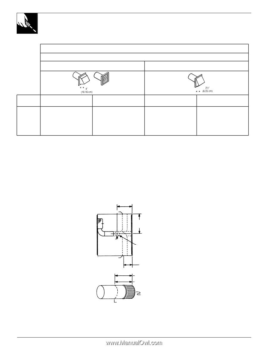
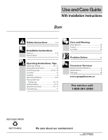
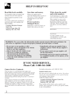
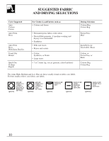
EXHAUST LENGTH CALCULATION Table 1: RECOMMENDED MAXIMUM LENGTH ELECTRIC DRYERS Recommended Weather Hood Type Use only for short run installations No. of 90˚ elbows 0 1 2 3 Rigid 14 m (46 ft.) 11 m (38 ft.) 9 m (31 ft.) 7 m (24 ft.) * Do not use non metallic flexible duct. Metallic Flexible* 9 m (30 ft.) 7.5 m (25 ft.) 6 m (20 ft.) 5 m (16 ft.) Rigid 11 m (37 ft.) 9 m (30 ft.) 6.5 m (22 ft.) 4.5 m (15 ft.) Metallic Flexible* 7 m (24 ft.) 6 m (20 ft.) 4 m (14 ft.) 3 m (10 ft.) ALTERNATE EXHAUST DIRECTIONS IF YOUR DRYER COMES WITH REAR EXHAUST, IF YOUR DRYER COMES WITH TOP EXHAUSTING, TO CHANGE TO SIDE OR DOWN EXHAUST: TO CHANGE TO SIDE OR REAR EXHAUST: • Remove access panel at back of dryer to gain access to • Remove rear access panel. internal ducts. • Disconnect retaining plate & 90˚ elbow by removing • Disconnect duct exhaust from blower housing (remove tape mounting screw from the chassis & remove tape securing securing duct). elbow to blower housing. FOR SIDE EXHAUST: • Remove desired knockout plate 152 mm • Remove cover plate from rear access panel and place over top exhaust opening. (either right or left side). • Cut a 115 mm (4 1/2") length of 6" Left knockout FOR SIDE EXHAUST: • Remove retaining plate attached to 90˚ elbow. 100 mm (4") dia. rigid duct as • Remove desired knockout plate (either right or shown (remove burrs from cut edge). • Attach this extension duct to Blower 203 mm (8") left side). • Cut a 115 mm (4 1/2") length of 100 mm (4") Front of dryer blower housing duct. dia. rigid duct as shown (remove burrs from • Attach a 90˚ elbow facing desired cut edge). opening. • Attach a section of 100 mm (4") Bottom knockout • Attach this extension duct to blower housing duct. dia. rigid duct to elbow to • Attach the 90˚ elbow facing desired opening. protrude thru side of cabinet. • Seal all joints with duct tape. • Reinstall rear access panel. FOR BOTTOM EXHAUST: • Remove cover plate at bottom of dryer. Right knockout 295 mm (115/8") 115 mm (41/2") 89 mm (31/2") For Rear Exhaust For Side Exhaust • Attach a section of 100 mm (4") dia. rigid duct to elbow to protude thru side of cabinet. • Seal all joints with duct tape. • Reinstall rear access panel. FOR REAR EXHAUST: • Cut a 295 mm (11 5/8") length of 100 mm (4") • Install a 90˚ elbow. dia. ridig duct as shown (remove burrs from • Seal all joints with duct tape. Rigid cutting edge). • Reinstall rear access panel. • Place cover plate (removed from Cut Here Metallic Ducting • Attach this extension duct to blower housing. • Seal all joints with duct tape. bottom of dryer) over rear exhaust EXTENSION DUCT • Reinstall rear access panel. opening. NOTE: Non-metallic ducts must never be used inside dryer cabinet. 6
-
 1
1 -
 2
2 -
 3
3 -
 4
4 -
 5
5 -
 6
6 -
 7
7 -
 8
8 -
 9
9 -
 10
10 -
 11
11 -
 12
12 -
13
-
14
-
15
-
16
-
17
-
18
-
19
-
20
-
21
-
22
-
23
-
24
-
25
-
26
-
27
-
28
-
29
-
30
-
31
-
32
 |
 |