GE PI6000 Installation Instructions - Page 2
Installing the Detector, Mounting Height Settings, Setting the Jumpers, Pet Applications - wiring
 |
UPC - 046188070398
View all GE PI6000 manuals
Add to My Manuals
Save this manual to your list of manuals |
Page 2 highlights
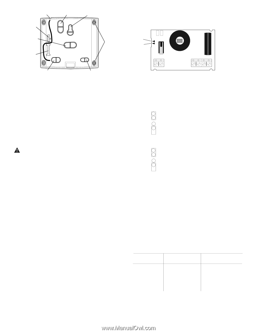
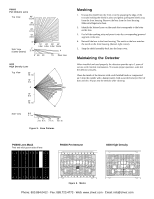
Wire entry hole for surface wire runs Primary wire entry hole for corner Primary mounting hole for flat wall mounting Locking tab Center wire entry hole Cable strain relief Mounting holes for corner mounting Additional wire entry hole Secondary mounting hole used to lock down when flat wall mounting Figure 3. Back Housing Jumpers J3 J4 PULSE 8/9' 7/8' 3 2 J3 J4 LED A PET B T T + - NC COM Power In 10 to 16 VDC Figure 4 . Circuit Board Installing the Detector 1. Select an appropriate mounting location. 2. Route wiring to the detector's location. 3. Open the detector and, after selecting appropriate mounting and wire entry options, remove the knockouts by depressing from the inside of the detector in the center of desired knockout (see Figure 3). The circuit board may be removed to facilitate mounting and removal of knockouts if desired. CAUTION You must be free of all electricity before handling sensor circuit boards. Touch a grounded bare metal surface before touching circuit boards or wear a grounding strap. Promptly reinstall the circuit board when finished with knockout removal and mounting the back housing. 4. Pull cable through the appropriate knockout and fasten the detector to the wall. 5. Strip back the outer jacket and individual wires of the cable and connect the conductors to the proper terminals (see Figure 4). The alarm contacts are not polarity sensitive. Note Use caution not to strip more insulation than needed, approximately 1/4" (0.6cm), so that bare wires do not touch and cause a short. 6. Route the cable through the strain relief located on the far left side of the back housing (see Figure 3). Snap on the front housing. 7. Walk test the detector and check for desired coverage. Note Most units walk test more accurately if the person testing waits 10 seconds between tripping the unit and walking again. This allows the detector to stabilize between trips. Mounting Height Settings The factory setting of the detector is for mounting heights of 7 to 8 feet (2.1 to 2.4m). For this setting, the locking tab on the back housing is in the notch by the 7-8' arrow on the circuit board (position A in Figure 4). For proper operation at mounting heights above 8 feet (2.4m), the locking tab must be in the notch by the 8-9' arrow (position B in Figure 4). Setting the Jumpers J3 Pulse Count - ON = Three-pulse mode OFF = Two-pulse mode (factory default) Note Use two-pulse mode for all residential applications including pet applications. J4 LED - ON = LED enabled (factory default) OFF = LED disabled Pet Applications A. For pet applications, the detector should be installed at the standard 7 to 8 feet (2.1 to 2.4m) mounting height. Verify that the circuit board is properly positioned in the back housing (see Mounting Height Settings). B. Place the pulse count selection jumper in two-pulse mode (see Setting the Jumpers). C. Make sure animals cannot get within 6 feet (1.8m) of the detector's line of sight or climb on furniture within 6 feet (1.8m) of the detector. Note False alarm immunity from any number of small pets and rodents can be expected as long as the total combined weight does not exceed 30 lbs. and room temperature does not fall below 50° F (10° C). Long Hair Up to 50 lbs Cocker Spaniel Eskimo Husky Pekinese Sheepdog Short Hair Up to 30 lbs Basenji Border Terrier French Bulldog Welsh Corgi Cats Not Recommmended Doberman Greyhound Mastiff Shepherd St. Bernard The pet immunity feature has not been tested by Underwriters Laboratories Inc. 6000 Series PIR Phone: 800.894.0412 - Fax: 888.723.4773 - Web: www.clrwtr.com - Email: [email protected]
-
 1
1 -
 2
2 -
 3
3 -
 4
4
 |
 |