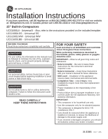
GE UCG1680LSS Installation Instructions - Page 6
Adjust Retaining Bracket, Adjusting The Base Toekick, Position Compactor Under, The Countertop,
 |
View all GE UCG1680LSS manuals
Add to My Manuals
Save this manual to your list of manuals |
Page 6 highlights
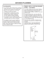
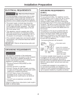
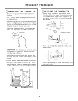
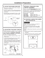
Installation Preparation 3 ADJUST RETAINING BRACKET • Determine installation depth of the compactor beneath the countertop. • Adjust the position of the retaining brackets so that the screws can meet the underside of the countertop. • Mounting clips are provided for stone or other hard countertops that will not accept screws. Countertop Retaining bracket 4 ADJUSTING THE BASE TOEKICK A toekick extension is supplied. It can be used to cover any gaps from the bottom of the compactor to the floor. (See the OPTIONAL STAINLESS STEEL TOEKICK ASSEMBLY section following this step for available accessories.) • Remove the toekick screws as shown. Lift off toekick piece. • Loosen the adjustable panel screws, adjust to touch the floor and tighten the screws. NOTE: If replacing with stainless steel assembly accessories, remove the screws and lift off. Install the new stainless steel toekick assembly accessories. • Reinstall the toekick piece with the original screws. OPTIONAL STAINLESS STEEL TOEKICK ASSEMBLY Order on-line at GEApplianceParts.com, 24 hours a day or by phone at 877.959.8688 during normal business hours. To replace the included black toekick assembly with a stainless steel toekick assembly, order the following three parts: Part Number WC17X10019 WC17X10011 WC17X10006 Accessory Kickplate - Stainless Steel Adjustable Panel - Stainless Steel Toekick - Stainless Steel 5 POSITION COMPACTOR UNDER THE COUNTERTOP CAUTION When moving the compactor, use gloves to protect and cushion your hands. To protect the finished flooring, use a dolly to move the compactor near the installation location. Failure to follow these instructions could result in injury. • Plug the power cord into a properly grounded receptacle. • Carefully lift the front of the compactor slightly and roll the unit into the cabinet opening. Lift here Toekick Adjustable Panel Loosen screw on each side 6
-
 1
1 -
 2
2 -
 3
3 -
 4
4 -
 5
5 -
 6
6 -
 7
7 -
 8
8 -
 9
9 -
 10
10 -
 11
11 -
 12
12 -
13
-
14
-
15
-
16
 |
 |
