Gigabyte 7NF-RZC User Manual - Page 14
FDD FDD Connector, IDE1 / IDE2 IDE1 / IDE2 Connector, PWR_LED
 |
View all Gigabyte 7NF-RZC manuals
Add to My Manuals
Save this manual to your list of manuals |
Page 14 highlights
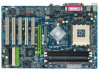
English 5) FDD (FDD Connector) The FDD connector is used to connect the FDD cable while the other end of the cable connects to the FDD drive. The types of FDD drives supported are: 360KB, 720KB, 1.2MB, 1.44MB and 2.88MB. Please connect the red power connector wire to the pin1 position. 33 1 34 2 6) IDE1 / IDE2 (IDE1 / IDE2 Connector) An IDE device connects to the computer via an IDE connector. One IDE connector can connect to one IDE cable, and the single IDE cable can then connect to two IDE devices (hard drive or optical drive). If you wish to connect two IDE devices, please set the jumper on one IDE device as Master and the other as Slave (for information on settings, please refer to the instructions located on the IDE device). 39 1 IDE1 IDE2 40 2 7) PWR_LED PWR_LED is connect with the system power indicator to indicate whether the system is on/off. It will blink when the system enters suspend mode. Pin No. Definition 1 1 MPD+ 2 MPD- 3 MPD- 7NF-RZ Series Motherboard - 14 -
-
 1
1 -
2
-
3
-
4
-
5
-
6
-
7
-
8
-
 9
9 -
 10
10 -
 11
11 -
 12
12 -
 13
13 -
 14
14 -
 15
15 -
 16
16 -
 17
17 -
 18
18 -
 19
19 -
20
-
21
-
22
-
23
-
24
-
25
-
26
-
27
-
28
-
29
-
30
-
31
-
32
-
33
-
34
-
35
-
36
-
37
-
38
-
39
-
40
 |
 |
