Gigabyte B650 AORUS ELITE AX ICE User Manual - Page 20
CPU_FAN/SYS_FAN1/2/3 Fan Headers, SYS_FAN4_PUMP System Fan/Water Cooling Pump Header, Connector
 |
View all Gigabyte B650 AORUS ELITE AX ICE manuals
Add to My Manuals
Save this manual to your list of manuals |
Page 20 highlights
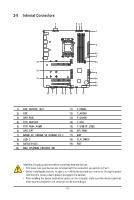
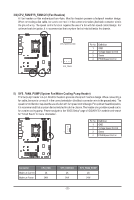
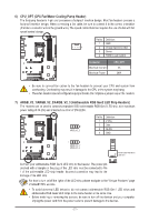
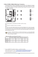
3/4) CPU_FAN/SYS_FAN1/2/3 (Fan Headers) All fan headers on this motherboard are 4-pin. Most fan headers possess a foolproof insertion design. When connecting a fan cable, be sure to connect it in the correct orientation (the black connector wire is the ground wire). The speed control function requires the use of a fan with fan speed control design. For optimum heat dissipation, it is recommended that a system fan be installed inside the chassis. 1 CPU_FAN/SYS_FAN1 1 SYS_FAN2/3 Pin No. 1 2 3 4 Definition GND Voltage Speed Control Sense PWM Speed Control 5) SYS_FAN4_PUMP (System Fan/Water Cooling Pump Header) The fan/pump header is 4-pin. Most fan headers possess a foolproof insertion design. When connecting a fan cable, be sure to connect it in the correct orientation (the black connector wire is the ground wire). The speed control function requires the use of a fan with fan speed control design. For optimum heat dissipation, it is recommended that a system fan be installed inside the chassis. The header also provides speed control for a water cooling pump. Please navigate to the "BIOS Setup" page of GIGABYTE's website and search for "Smart Fan 6" for more information. Pin No. Definition 1 GND 2 Voltage Speed Control 1 3 Sense 4 PWM Speed Control Connector Maximum Current Maximum Power CPU_FAN 2A 24W SYS_FAN1/2/3 2A 24W SYS_FAN4_PUMP 2A 24W - 20 -
-
 1
1 -
2
-
3
-
4
-
5
-
6
-
7
-
8
-
9
-
10
-
11
-
12
-
13
-
14
-
 15
15 -
 16
16 -
 17
17 -
 18
18 -
 19
19 -
 20
20 -
 21
21 -
 22
22 -
 23
23 -
 24
24 -
 25
25 -
26
-
27
-
28
-
29
-
30
-
31
-
32
-
33
-
34
-
35
-
36
-
37
 |
 |
