Gigabyte B650 AORUS ELITE AX ICE User Manual - Page 21
CPU_OPT CPU Fan/Water Cooling Pump Header
 |
View all Gigabyte B650 AORUS ELITE AX ICE manuals
Add to My Manuals
Save this manual to your list of manuals |
Page 21 highlights
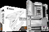
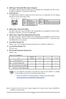
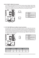
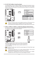
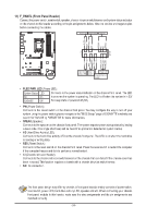
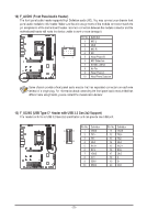
B_ SF _ _ B_ USB 0_ B 6) CPU_OPT (CPU Fan/Water Cooling Pump Header) The fan/pump header is 4-pin and possesses a foolproof insertion design. Most fan headers possess a foolproof insertion design. When connecting a fan cable, be sure to connect it in the correct orientation (the black connector wire is the ground wire). The speed control function requires the use of a fan with fan speed control design. S _S Pin No. Definition _ 1 GND 1 2 Voltage Speed Control 3 Sense 4 PWM Speed Control Connector Maximum Current Maximum Power CPU_OPT 2A 24W U _0 _F _0 F F_USB3 _ _B F_USB30 3 B •• Be sure to connect fan cables to the fan headers to prevent your CPU and system from overheating. Overheating may result in damage to the CPU or the system may hang. •• These fan headers are not configuration jumper blocks. Do not place a jumper cap on the headers. _ _3 S F_ S S_F B_ F_ F_ _ 7) ARGB_V2_1/ARGB_V2_2/ARGB_V2_3 (Addressable RGB Gen2 LED Strip Headers) The headers can be used to connect a standard 5050 addressable RGB Gen2 LED strip, with maximum power rating of 3A (5V) and maximum number of 256 LEDs. F _ 1 ARGB_V2_2 Pin No. 1 2 3 4 Definition V (5V) Data No Pin GND S_ S_ _ 1 ARGB_V2_1/ ARGB_V2_3 Addressable RGB Gen2 LED Strip F_ F_ F S S_F B_ _ S F_ _3 _ B 1 Connect your addressable RGB Gen2 LED strip to the header. The power pin (marked with a triangle on the plug) of the LED strip must be connected to Pin 1 of the addressable LED strip header. Incorrect connection may lead to the damage of the LED strip. For how to turn on/off the lights of the LED strip, please navigate to the "Unique Features" page of GIGABYTE's website. •• To avoid abnormal LED behavior, do not connect addressable RGB Gen1 LED strips and addressable RGB Gen2 LED strips to the same header at the same time. •• Before installing or removing the devices, be sure to turn off the devices and your computer. Unplug the power cord from the power outlet to prevent damage to the devices. U - 21 - _ _B F_USB30 3 F_USB3 _0 _F _0 F _ B_
-
 1
1 -
2
-
3
-
4
-
5
-
6
-
7
-
8
-
9
-
10
-
11
-
12
-
13
-
14
-
15
-
 16
16 -
 17
17 -
 18
18 -
 19
19 -
 20
20 -
 21
21 -
 22
22 -
 23
23 -
 24
24 -
 25
25 -
 26
26 -
27
-
28
-
29
-
30
-
31
-
32
-
33
-
34
-
35
-
36
-
37
 |
 |
