Gigabyte GA-6LISL Manual - Page 7
ASPEED 2300 BMC chipset
 |
View all Gigabyte GA-6LISL manuals
Add to My Manuals
Save this manual to your list of manuals |
Page 7 highlights
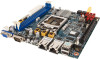
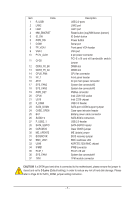
Item Code 1 R_USB1 2 LAN2 3 LAN1 4 NMI_BMCRST 5 ID_SW 6 PWR_SW 7 COM1 8 FP_VGA1 9 VGA1 10 P12V_AUX1 11 CFG5 12 DDR3_P0_B0 13 DDR3_P0_A0 14 CPU0_FAN 15 FP_1 16 ATX1 17 SYS_FAN2 18 SYS_FAN3 19 PWR_DET 20 CPU0 21 U516 22 F_USB3 23 SATA_DOM4 24 CASE_OPEN 25 BAT 26 SATA0~4 27 F_USB2_1 28 SATA_SGPIO 29 CLRCMOS 30 ME_UPDATE 31 BIOSRCVR 32 BMC_LED1 33 U546 34 IPMB1 35 PCIE_1 36 SYS_FAN1 37 TPM Description USB 2.0 ports LAN2 port LAN1 port Reset button (top)/NMI button (bottom) ID Switch button Power button Serial port Front panel VGA header VGA port 4 pin power connector PCI-E x16 and x8 bandwidth switch jumper DIMM slot DIMM slot CPU fan connector Front panel header 24 pin main power connector System fan connector#2 System fan connector#3 PMBus connector Intel LGA1150 socket Intel C226 chipset USB 3.0 header SATA port 4 DOM support jumper Case open intrusion header Battery power cable connector SATA 6Gb/s connectors USB 2.0 header SATA SGPIO header Clear CMOS jumper ME Update jumper BIOS recovery jumper BMC readiness LED ASPEED 2300 BMC chipset IPMB connector PCI-E x16 slot System fan connector#1 TPM module connector CAUTION! If a SATA type hard drive is connected to the motherboard, please ensure the jumper is closed and set to 2-3 pins (Default setting), in order to reduce any risk of hard disk damage. Please refer to Page 30 for SATA_DOM4 jumper setting instruction. - 7 -
-
 1
1 -
 2
2 -
 3
3 -
 4
4 -
 5
5 -
 6
6 -
 7
7 -
 8
8 -
 9
9 -
 10
10 -
 11
11 -
 12
12 -
13
-
14
-
15
-
16
-
17
-
18
-
19
-
20
-
21
-
22
-
23
-
24
-
25
-
26
-
27
-
28
-
29
-
30
-
31
-
32
-
33
-
34
-
35
-
36
-
37
-
38
-
39
-
40
-
41
-
42
-
43
-
44
-
45
-
46
-
47
-
48
-
49
-
50
-
51
-
52
-
53
-
54
-
55
-
56
-
57
-
58
-
59
-
60
-
61
-
62
-
63
-
64
-
65
-
66
-
67
-
68
-
69
-
70
-
71
-
72
-
73
-
74
-
75
-
76
-
77
-
78
-
79
-
80
-
81
-
82
-
83
-
84
-
85
-
86
-
87
-
88
-
89
-
90
-
91
-
92
-
93
-
94
-
95
-
96
 |
 |
