Gigabyte GA-7PCSL Manual - Page 32
FP_1 Front Panel Header/GA-7PCSL
 |
View all Gigabyte GA-7PCSL manuals
Add to My Manuals
Save this manual to your list of manuals |
Page 32 highlights
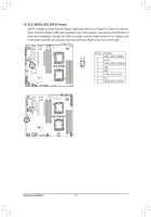
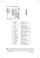
15) FP_1 (Front Panel Header/GA-7PCSL) Connect the power switch, reset switch, speaker, chassis intrusion switch/sensor and system status indicator on the chassis to this header according to the pin assignments below. Note the positive and negative pins before connecting the cables. 12 GA-7PCSL 12 24 Pin No. 1 2 3 4 5 6 7 8 9 10 11 12 13 14 15 16 17 18 19 20 21 22 23 24 Signal Name PWLED+ 5VSB NC ID_LED+ PWLED- ID_LED- HD+ F_SYSRDY HD- (GND) SYS_STATUS- PWB+ L2_ACT PWB+_GND L2_LINK- RST_BTN+ SENSOR_SDA RST_BTN_GND SENSOR_SCL ID_SW+ CASE_OPEN- ID_SW (GND) L1_ACT NMI_SW- L1_LINK- Definition Power LED Signal anode (+) 5V Stanndby Power No Pin ID LED Signal anode (+) Power LED Signal cathode(-) ID LED Signal cathode(-) Hard Disk LED Signal anode (+) System Front board LED Signal Ground System Status LED Signal cathode(-) Power Button Signal anode (+) LAN2 active LED Signal Ground LAN2 Link LED Signal cathode(-) Reset button Signal anode (+) SMBus Data Signal Ground SMBus Clock Signal ID Switch Signal anode (+) Chassis intrusion Signal cathode(-) Ground LAN1 active LED Signal NMI switch Signal cathode(-) LAN1 Link LED Signal cathode(-) - 32 - Hardware Installation
-
 1
1 -
2
-
3
-
4
-
5
-
6
-
7
-
8
-
9
-
10
-
11
-
12
-
13
-
14
-
15
-
16
-
17
-
18
-
19
-
20
-
21
-
22
-
23
-
24
-
25
-
26
-
 27
27 -
 28
28 -
 29
29 -
 30
30 -
 31
31 -
 32
32 -
 33
33 -
 34
34 -
 35
35 -
 36
36 -
 37
37 -
38
-
39
-
40
-
41
-
42
-
43
-
44
-
45
-
46
-
47
-
48
-
49
-
50
-
51
-
52
-
53
-
54
-
55
-
56
-
57
-
58
-
59
-
60
-
61
-
62
-
63
-
64
-
65
-
66
-
67
-
68
-
69
-
70
-
71
-
72
-
73
-
74
-
75
-
76
-
77
-
78
-
79
-
80
-
81
-
82
-
83
-
84
-
85
-
86
-
87
-
88
-
89
-
90
-
91
 |
 |
