Gigabyte GA-7PESH2 Manual - Page 7
DDR3_P1_E1 - it mode
 |
View all Gigabyte GA-7PESH2 manuals
Add to My Manuals
Save this manual to your list of manuals |
Page 7 highlights
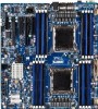
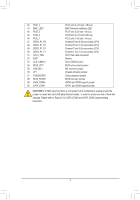
42 PCIE_4 43 BMC_LED1 44 PCIE_3 45 PCIE_2 46 PCIE_1 47 DDR3_P1_E0 48 DDR3_P1_E1 49 DDR3_P1_F0 50 DDR3_P1_F1 51 CPU1_FAN 52 BAT1 53 CLR_CMOS1 54 BIOS_WP1 55 SSB_ME1 56 JP1 57 PASSWORD1 58 BIOS_RVCR1 59 SATA_DOM0 60 SATA_DOM1 PCI-E slot 4 (x16 slot / x8 bus) BMC firmware readiness LED PCI-E slot 3 (x8 slot / x4 bus) PCI-E slot 2 (x16 slot/x16 bus) PCI-E slot 1 (x8 slot / x4 bus) Channel E slot 0 (for secondary CPU) Channel E slot 1 (for secondary CPU) Channel F slot 0 (for secondary CPU) Channel F slot 1 (for secondary CPU) CPU1 fan cable connector Battery Clear CMOS jumper BIOS write protect jumper ME recovery jumper Chassis intrusion jumper Clear password jumper BIOS recovery jumper SATA0 port DOM support jumper SATA1 port DOM support jumper CAUTION! If a SATA type hard drive is connected to the motherboard, please ensure the jumper is closed and set to 2-3 pins (Normal mode), in order to reduce any risk of hard disk damage. Please refer to Page 33 for SATA_DOM0 and SATA_DOM1 jumper setting instruction. - 7 -
-
 1
1 -
 2
2 -
 3
3 -
 4
4 -
 5
5 -
 6
6 -
 7
7 -
 8
8 -
 9
9 -
 10
10 -
 11
11 -
 12
12 -
13
-
14
-
15
-
16
-
17
-
18
-
19
-
20
-
21
-
22
-
23
-
24
-
25
-
26
-
27
-
28
-
29
-
30
-
31
-
32
-
33
-
34
-
35
-
36
-
37
-
38
-
39
-
40
-
41
-
42
-
43
-
44
-
45
-
46
-
47
-
48
-
49
-
50
-
51
-
52
-
53
-
54
-
55
-
56
-
57
-
58
-
59
-
60
-
61
-
62
-
63
-
64
-
65
-
66
-
67
 |
 |