Gigabyte GA-7PESH3 Manual - Page 8
Force to Stop FRB1 Timer jumper
 |
View all Gigabyte GA-7PESH3 manuals
Add to My Manuals
Save this manual to your list of manuals |
Page 8 highlights
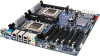
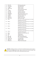
45 BIOS_WP1 46 CLR_CMOS1 47 F_USB3_1 48 FRONT_USB 49 BP_1 50 F_PANEL1 51 SYS_FAN4 52 SYS_FAN3 53 PASSWORD1 54 S3_MASK 55 SSB_ME1 56 Chassis_OP 57 BIOS_RVCR1 58 PCIE_1 59 PCIE_2 60 PCIE_3 61 PCIE_4 62 PCIE_5 63 PCIE_6 64 PCIE_7 65 IPMB1 66 U47 67 BMC_LED1 68 BMC_FRB1 69 FAUDIO_ACZ 70 SPDIF_OUT 71 PMBUS_SEL BIOS write protect jumper Clear CMOS jumper USB 3.0 connector USB 2.0 connector HDD back plane board header Front pannel header Systen fan connector #4 Systen fan connector #4 Skip supervisor paswword jumper S3 Power On Select jumper ME recovery jumper Chassis intrusion header BIOS recovery jumper PCI-E slot 1 (x16 slot/Running at x8; shared bandwidth with PCI-E slot 2) PCI-E slot 2 (x16 slot/Running at x8; shared bandwidth with PCI-E slot 1) PCI-E slot 3 (x16 slot/Running at x8; shared bandwidth with PCI-E slot 4) PCI-E slot 4 (x16 slot/Running at x8; shared bandwidth with PCI-E slot 3) PCI-E slot 5 (x16 slot/Running at x8; shared bandwidth with PCI-E slot 6) PCI-E slot 6 (x16 slot/Running at x8; shared bandwidth with PCI-E slot 3) PCI-E slot 7 (x16 slot/Running at x16) IPMB connector ASPEED AST2300 BMC firmware readiness LED Force to Stop FRB1 Timer jumper Front audio header S/PDIF Out header PMBus Power Select jumper CAUTION! If a SATA type hard drive is connected to the motherboard, please ensure the jumper is closed and set to 2-3 pins (Normal mode), in order to reduce any risk of hard disk damage. Please refer to Page 38 for SATA_DOM1 and SATA_DOM2 jumper setting instruction. - 8 -
-
 1
1 -
2
-
 3
3 -
 4
4 -
 5
5 -
 6
6 -
 7
7 -
 8
8 -
 9
9 -
 10
10 -
 11
11 -
 12
12 -
 13
13 -
14
-
15
-
16
-
17
-
18
-
19
-
20
-
21
-
22
-
23
-
24
-
25
-
26
-
27
-
28
-
29
-
30
-
31
-
32
-
33
-
34
-
35
-
36
-
37
-
38
-
39
-
40
-
41
-
42
-
43
-
44
-
45
-
46
-
47
-
48
-
49
-
50
-
51
-
52
-
53
-
54
-
55
-
56
-
57
-
58
-
59
-
60
-
61
-
62
-
63
-
64
-
65
-
66
-
67
-
68
-
69
-
70
-
71
-
72
-
73
-
74
-
75
-
76
-
77
-
78
 |
 |
