Gigabyte GA-8IP775 Manual - Page 13
Installation of the Heatsink - manual
 |
View all Gigabyte GA-8IP775 manuals
Add to My Manuals
Save this manual to your list of manuals |
Page 13 highlights
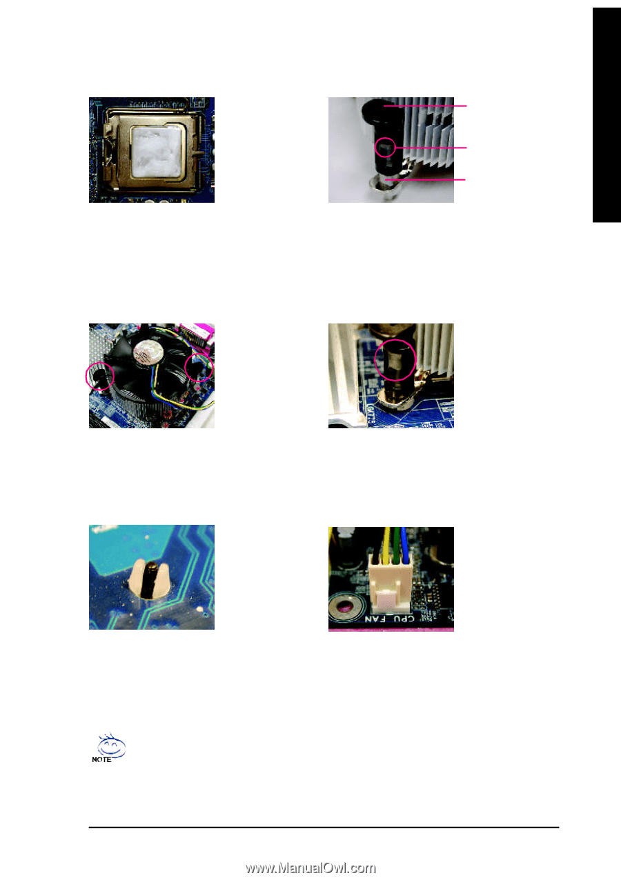
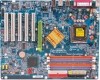
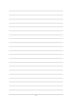
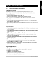
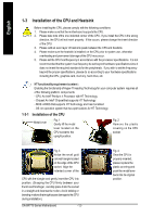
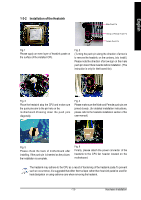
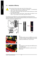
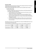
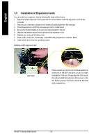
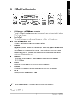
English 1-3-2 Installation of the Heatsink Male Push P in The top of Female P ush P in Female Push P in Fig.1 Please apply an even layer of heatsink paste on the surface of the installed CPU. Fig. 2 (Turning the push pin along the direction of arrow is to remove the heatsink, on the contrary, is to install.) Please note the direction of arrow sign on the m ale push pin doesn't face inwards before installation. (This instruction is only for Intel boxed fan) Fig. 3 Place the heatsink atop the CPU and m ake sure the push pins aim to the pin hole on the m otherboard.Pressing down the push pins diagonally. Fig. 4 Please make sure the Male and Female push pin are joined closely. (for detailed installation instructions, please refer to the heatsink installation section of the user manual) Fig. 5 Please check the back of m otherboard after installing. If the push pin is inserted as the picture, the installation is complete. Fig. 6 Finally, please attach the power connector of the heatsink to the CPU fan header located on the m otherboard. The heatsink may adhere to the CPU as a result of hardening of the heatsink paste.To prevent such an occurrence, it is suggested that either thermal tape rather than heat sink paste be used for heat dissipation or using extreme care when removing the heatsink. - 13 - Hardware Installation
-
 1
1 -
2
-
3
-
4
-
5
-
6
-
7
-
 8
8 -
 9
9 -
 10
10 -
 11
11 -
 12
12 -
 13
13 -
 14
14 -
 15
15 -
 16
16 -
 17
17 -
 18
18 -
19
-
20
-
21
-
22
-
23
-
24
-
25
-
26
-
27
-
28
-
29
-
30
-
31
-
32
-
33
-
34
-
35
-
36
-
37
-
38
-
39
-
40
-
41
-
42
-
43
-
44
-
45
-
46
-
47
-
48
-
49
-
50
-
51
-
52
-
53
-
54
-
55
-
56
-
57
-
58
-
59
-
60
-
61
-
62
-
63
-
64
-
65
-
66
-
67
-
68
-
69
-
70
-
71
-
72
-
73
-
74
-
75
-
76
-
77
-
78
-
79
-
80
 |
 |