Gigabyte GA-8SIMLH User Manual - Page 20
CPU_FAN CPU FAN Connector, SYS_FAN System FAN Connector, ATX_12V +12V Power Connector, ATX ATX Power
 |
View all Gigabyte GA-8SIMLH manuals
Add to My Manuals
Save this manual to your list of manuals |
Page 20 highlights
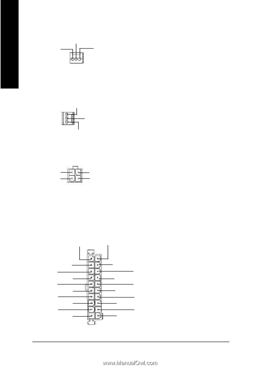
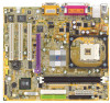
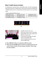
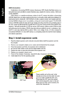
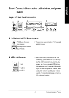
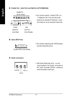
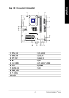
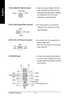
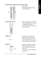
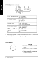
English 1) CPU_FAN (CPU FAN Connector) +12V/C ontrol Sense GND 1 Ø Please note, a proper installation of the CPU cooler is essential to prevent the CPU from running under abnormal condition or damaged by overheating.The CPU fan connector supports Max. current up to 600 mA. 2) SYS_FAN (System FAN Connector) Sense 1 +12V/C ontrol GND Ø This connector allows you to link with the cooling fan on the system case to lower the system temperature. 3) ATX_12V ( +12V Power Connector) 34 +12V GND 12 +12V GND ØThis connector (ATX +12V) supplies the CPU operation voltage (Vcore). If this " ATX+ 12V connector" is not connected, system cannot boot. 4) ATX (ATX Power) 3.3V 3.3V 1 Ø AC power cord should only be connected to your power supply unit after ATX power cable and other related devices are firmly connected to the mainboard. -12V GND PS-ON(Soft On/Off) GND GND GND -5V VCC VCC 20 3.3V GND VCC GND VCC GND Power Good 5V SB (Stand by +5V) +12V GA-8SIMLH Motherboard - 16 -
-
 1
1 -
2
-
3
-
4
-
5
-
6
-
7
-
8
-
9
-
10
-
11
-
12
-
13
-
14
-
 15
15 -
 16
16 -
 17
17 -
 18
18 -
 19
19 -
 20
20 -
 21
21 -
 22
22 -
 23
23 -
 24
24 -
 25
25 -
26
-
27
-
28
-
29
-
30
-
31
-
32
-
33
-
34
-
35
-
36
-
37
-
38
-
39
-
40
-
41
-
42
-
43
-
44
-
45
-
46
-
47
-
48
-
49
-
50
-
51
-
52
-
53
-
54
-
55
-
56
-
57
-
58
-
59
-
60
-
61
-
62
-
63
-
64
-
65
-
66
-
67
-
68
-
69
-
70
-
71
-
72
-
73
-
74
-
75
-
76
-
77
-
78
-
79
-
80
-
81
-
82
-
83
 |
 |