Gigabyte GA-8SIMLH User Manual - Page 22
F_PANEL 2x10 pins Connector, BAT1 Battery, CAUTION
 |
View all Gigabyte GA-8SIMLH manuals
Add to My Manuals
Save this manual to your list of manuals |
Page 22 highlights
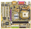
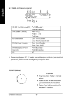
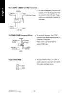
English 9) F_PANEL (2x10 pins Connector) MPD+ MPDPW+ PWSPK+ SPK- 21 1 1 20 11 1 19 HD+ HDRSTRST+ NC HD (IDE Hard Disk Activ e LED) SPK (Speaker Connector) RST (Reset Switch) PW (Soft Power Connector) MPD(Message LED/Power/ Sleep LED) NC Pin 1: LED anode(+) Pin 2: LED cathode(-) Pin 1: VCC(+) Pin 2- Pin 3: NC Pin 4: Data(-) Open: Normal Operation Close: Reset Hardware System Open: Normal Operation Close: Power On/Off Pin 1: LED anode(+) Pin 2: LED cathode(-) NC Ø Please connect the power LED, PC speaker, reset switch andpower switch etc of your chassis front panel to the F_PANEL connector according to the pin assignment above. 10) BAT1 (Battery) + GA-8SIMLH Motherboard CAUTI ON v Danger of explosion if battery is incorrectly replaced. v Replace only with the same or equivalent type recommended by the manufacturer. v Dispose of used batteries according to the manufacturer's instructions. - 18 -
-
 1
1 -
2
-
3
-
4
-
5
-
6
-
7
-
8
-
9
-
10
-
11
-
12
-
13
-
14
-
15
-
16
-
 17
17 -
 18
18 -
 19
19 -
 20
20 -
 21
21 -
 22
22 -
 23
23 -
 24
24 -
 25
25 -
 26
26 -
 27
27 -
28
-
29
-
30
-
31
-
32
-
33
-
34
-
35
-
36
-
37
-
38
-
39
-
40
-
41
-
42
-
43
-
44
-
45
-
46
-
47
-
48
-
49
-
50
-
51
-
52
-
53
-
54
-
55
-
56
-
57
-
58
-
59
-
60
-
61
-
62
-
63
-
64
-
65
-
66
-
67
-
68
-
69
-
70
-
71
-
72
-
73
-
74
-
75
-
76
-
77
-
78
-
79
-
80
-
81
-
82
-
83
 |
 |
