Gigabyte GA-A320-DS3 User Manual - Page 17
COM Serial Port Header, TPM Trusted Platform Module Header, CLR_CMOS Clear CMOS Jumper
 |
View all Gigabyte GA-A320-DS3 manuals
Add to My Manuals
Save this manual to your list of manuals |
Page 17 highlights
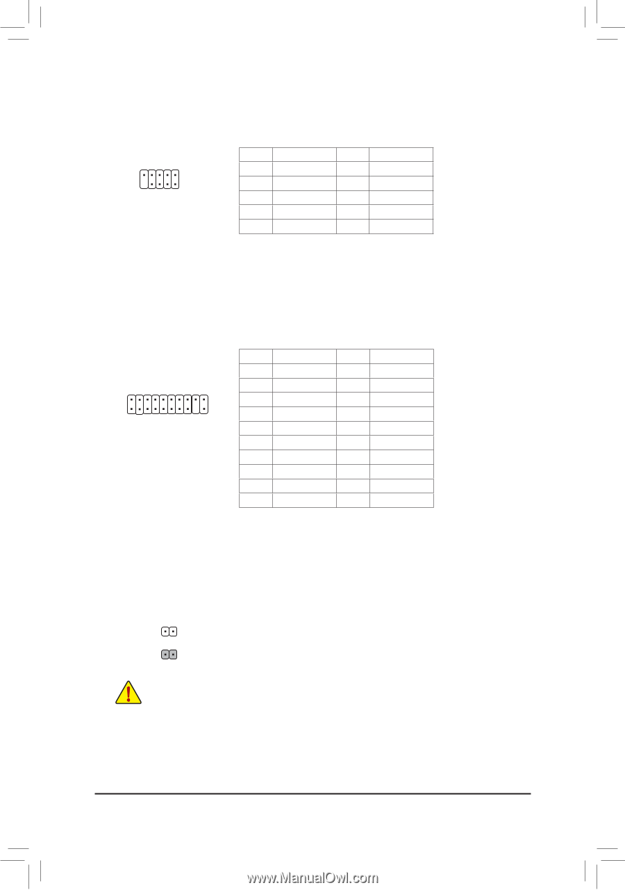
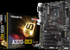
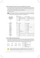
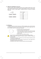
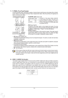
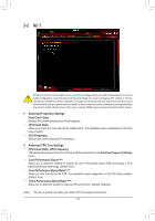
12) COM (Serial Port Header) The COM header can provide one serial port via an optional COM port cable. For purchasing the optional COM port cable, please contact the local dealer. 9 1 10 2 Pin No. 1 2 3 4 5 Definition NDCDNSIN NSOUT NDTRGND Pin No. 6 7 8 9 10 Definition NDSRNRTSNCTSNRINo Pin G.QBOFM DEBUG PORT 13) TPM (Trusted Platform Module Header) You may connect a TPM (Trusted Platform Module) to this header. Pin No. Definition Pin No. Definition 1 LCLK 11 LAD0 2 GND 12 GND 19 1 3 LFRAME 13 NC 20 2 4 No Pin 14 NC 5 LRESET 15 SB3V 6 NC 16 SERIRQ 7 LAD3 17 GND 8 LAD2 18 NC 9 VCC3 19 NC 10 LAD1 20 NC 14) CLR_CMOS (Clear CMOS Jumper) Use this jumper to clear the BIOS configuration and reset the CMOS values to factory defaults. To clear the CMOS values, use a metal object like a screwdriver to touch the two pins for a few seconds. Open: Normal Short: Clear CMOS Values •• Always turn off your computer and unplug the power cord from the power outlet before clearing the CMOS values. •• After system restart, go to BIOS Setup to load factory defaults (select Load Optimized Defaults) or manually configure the BIOS settings (refer to Chapter 2, "BIOS Setup," for BIOS configurations). - 17 -
-
 1
1 -
2
-
3
-
4
-
5
-
6
-
7
-
8
-
9
-
10
-
11
-
 12
12 -
 13
13 -
 14
14 -
 15
15 -
 16
16 -
 17
17 -
 18
18 -
 19
19 -
 20
20 -
 21
21 -
 22
22 -
23
-
24
-
25
-
26
-
27
-
28
-
29
-
30
-
31
-
32
-
33
-
34
-
35
-
36
-
37
-
38
-
39
 |
 |