Gigabyte GA-B150N-GSM User Manual - Page 17
F_USB30 USB 3.0/2.0 Header, SPEAKER Speaker Header, SPDIF_O S/PDIF Out Header
 |
View all Gigabyte GA-B150N-GSM manuals
Add to My Manuals
Save this manual to your list of manuals |
Page 17 highlights
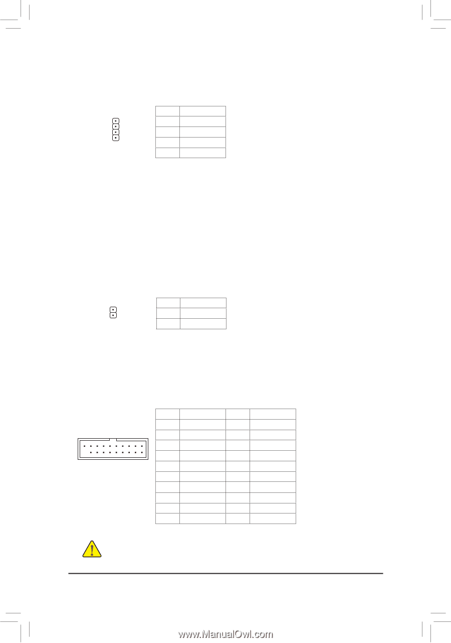
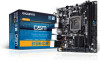
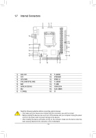
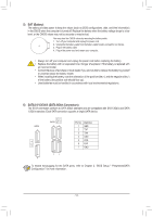
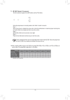
10) SPEAKER (Speaker Header) Connects to the speaker on the chassis front panel. The system reports system startup status by issuing a beep code. One single short beep will be heard if no problem is detected at system startup. Pin No. Definition 1 VCC 2 NC 1 3 NC 4 SPK- 11) SPDIF_O (S/PDIF Out Header) This header supports digital S/PDIF Out and connects a S/PDIF digital audio cable (provided by expansion cards) for digital audio output from your motherboard to certain expansion cards like graphics cards and sound cards. For example, some graphics cards may require you to use a S/PDIF digital audio cable for digital audio output from your motherboard to your graphics card if you wish to connect an HDMI display to the graphics card and have digital audio output from the HDMI display at the same time. For information about connecting the S/PDIF digital audio cable, carefully read the manual for your expansion card. Pin No. Definition 1 SPDIFO 1 2 GND 12) F_USB30 (USB 3.0/2.0 Header) The header conforms to USB 3.0/2.0 specification and can provide two USB ports. For purchasing the optional 3.5" front panel that provides two USB 3.0/2.0 ports, please contact the local dealer. Pin No. Definition Pin No. Definition 1 VBUS 11 D2+ 1 10 2 SSRX1- 12 D2- F_USB30 3 F_ USSRX1+ 13 GND F_ 4 GND 14 SSTX2+ 20 11 5 SSTX1- 15 SSTX2- 6 SSTX1+ 16 GND 7 GND 17 SSRX2+ 8 D1- 18 SSRX2- 9 D1+ 19 VBUS 10 NC 20 No Pin Prior to installing the USB bracket, be sure to turn off your computerBanSdSunplug the power cord from the power outlet to prevent damage to thBe_ USB bracket. 1 _S - 17 - S 1 23 1 1 23 1 1 1
-
 1
1 -
2
-
3
-
4
-
5
-
6
-
7
-
8
-
9
-
10
-
11
-
 12
12 -
 13
13 -
 14
14 -
 15
15 -
 16
16 -
 17
17 -
 18
18 -
 19
19 -
 20
20 -
 21
21 -
 22
22 -
23
-
24
-
25
-
26
-
27
-
28
-
29
-
30
-
31
-
32
-
33
-
34
-
35
-
36
-
37
-
38
-
39
-
40
 |
 |