Gigabyte GA-B150N-GSM User Manual - Page 7
x audio jacks Center/Subwoofer Speaker Out, Rear Speaker Out, Side Speaker, PnP 1.0a, DMI 2.7, WfM 2.0
 |
View all Gigabyte GA-B150N-GSM manuals
Add to My Manuals
Save this manual to your list of manuals |
Page 7 highlights
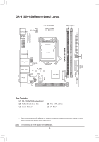
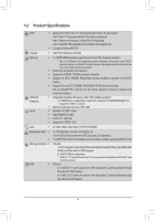
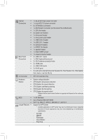
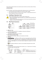
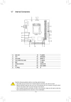
Internal Š Connectors Š Š Š Š Š Š Š Š Š Š Š Š Š Š Back Panel Š Connectors Š Š Š Š Š Š I/O Controller Š Hardware Š Monitor Š Š Š Š Š BIOS Š Š Š Unique Features Š 1 x 24-pin ATX main power connector 1 x 4-pin ATX 12V power connector 6 x SATA 6Gb/s connectors 1 x M.2 Socket 3 connector (on the back of the motherboard) 1 x CPU fan header 2 x system fan headers 1 x front panel header 1 x front panel audio header 1 x USB 3.0/2.0 header 1 x USB 2.0/1.1 header 4 x serial port headers 1 x S/PDIF Out header 1 x speaker header 1 x Clear CMOS jumper 1 x chassis intrusion header 2 x USB 2.0/1.1 ports 1 x PS/2 keyboard/mouse port 2 x Wi-Fi antenna connector holes 2 x HDMI ports 4 x USB 3.0/2.0 ports 2 x RJ-45 ports 6 x audio jacks (Center/Subwoofer Speaker Out, Rear Speaker Out, Side Speaker Out, Line In, Line Out, Mic In) iTE® I/O Controller Chip System voltage detection CPU/System temperature detection CPU/System fan speed detection CPU/System overheating warning CPU/System fan fail warning CPU/System fan speed control * Whether the fan speed control function is supported will depend on the cooler you install. 1 x 64 Mbit flash Use of licensed AMI UEFI BIOS PnP 1.0a, DMI 2.7, WfM 2.0, SM BIOS 2.7, ACPI 5.0 Support for APP Center * Available applications in APP Center may vary by motherboard model. Supported functions of each application may also vary depending on motherboard specifications. - 3D OSD - @BIOS - AutoGreen - Cloud Station - EasyTune - 7 -
-
 1
1 -
 2
2 -
 3
3 -
 4
4 -
 5
5 -
 6
6 -
 7
7 -
 8
8 -
 9
9 -
 10
10 -
 11
11 -
 12
12 -
13
-
14
-
15
-
16
-
17
-
18
-
19
-
20
-
21
-
22
-
23
-
24
-
25
-
26
-
27
-
28
-
29
-
30
-
31
-
32
-
33
-
34
-
35
-
36
-
37
-
38
-
39
-
40
 |
 |
