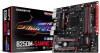
Gigabyte GA-B250M-Gaming 5 Users Manual - Page 16
M2Q_32G M.2 Socket 3 Connector, Installation Notices for the M2Q_32G and SATA Connectors
 |
View all Gigabyte GA-B250M-Gaming 5 manuals
Add to My Manuals
Save this manual to your list of manuals |
Page 16 highlights
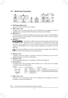
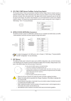
_ B F_USB3 F F _0 8) SPDIF_O (S/PDIF Out Header) This header supports digital S/PDIF Out and connects a S/PDIF digital audio cable (provided by expansion cards) for digital audio output from your motherboard to certain expansion cards like graphics cards and sound cards. For example, some graphics cards may require you to use a S/PDIF digital audio cable for digital audio output from your motherbo_aFrd to your graphics card if you wish to connect an HDMI display to the graphics card and have digital audio output from the HDMI display at the same time. For information about connecting the S/PDIF digital audio cable, carefully read the manual for your expansion card. Pin No. Definition 1 1 SPDIFO 2 G_N0D F 9) M2Q_32G (M.2 Socket 3 Connector) The M.2 connector supports M.2 SATA SSDs and M.2 PCIe SSDs. 110 80 60 42 Follow the steps below to correctly install an M.2 SSD in the M.2 connector. Step 1: Use a screw driver to unfasten the screw and nut from the motherboard. Locate the proper mounting hole for the M.2 SSD to be installed and then screw the nut first. Step 2: Slide the M.2 SSD into the connector at an angle. Step 3: Press the M.2 SSD down and then secure it with the screw. Select the proper hole for the M.2 SSD to be installed and refasten the screw and nut. Installation Notices for the M2Q_32G and SATA Connectors: Due to the limited number of lanes provided by the Chipset, the availability of the SATA connectors may be affected by the type of device installed in the M2Q_32G connector. The M2Q_32G connector shares bandwidth with the SATA3 5 connector. Refer to the following table for details. Type of M.2 SSD Connector SATA3 0 SATA3 1 SATA3 2 SATA3 3 SATA3 4 SATA3 5 M.2 SATA SSD a a a a a r M.2 PCIe x4 SSD a a a a a a M.2 PCIe x2 SSD a a a a a a No M.2 SSD Installed a a a a a a a: Available, r: Not available - 16 -
-
 1
1 -
2
-
3
-
4
-
5
-
6
-
7
-
8
-
9
-
10
-
 11
11 -
 12
12 -
 13
13 -
 14
14 -
 15
15 -
 16
16 -
 17
17 -
 18
18 -
 19
19 -
 20
20 -
 21
21 -
22
-
23
-
24
-
25
-
26
-
27
-
28
-
29
-
30
-
31
-
32
-
33
-
34
-
35
-
36
-
37
-
38
-
39
-
40
-
41
-
42
-
43
-
44
 |
 |
